Hey guys!
Finally found the time to build them, took over 25 hours in the end!
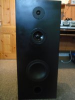
Bass driver is in a 44L ported box (66mm diameter, 186mm long), midrange in a 7L sealed (as per website).
Made out of 3/4 inch MDF, double thickness front wall, each join glues on at least 2 faces and screwed the same, if not from more! Sprayed black.
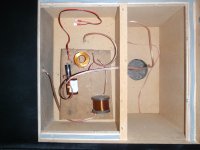
Crossover's wired in (Not the nicest of looking jobs, but that doesn't matter...), Zobel soldered directly to back of 5" mid.
Treble sounds really good, 8" in 44L sounds really nice, strong deep bass, 5" midrange is good when it’s used as a midrange, however has a really nasty boomy crappy sound when deep loud bass occurs (Which is predominantly the style of music that I listen to....)
Now is this a con of having a 2.5 way setup as opposed to a 3? Is there anything I can really do to reduce the mid from making this sound without doing a 3 way conversion?
One thing that did worry me slightly in construction was due to the size of the 44L, it meant the 7L for the midrange had to have its depth reduced to 100mm to make it fit within the space confines... This only leaves 40mm of air at the back once the driver has been fitted. Could this possibly be an issue? If it is I will just have to live with it....
Chucked a couple of photos up for those interested, if you want anymore just tell me =)
Cheers guys and thanks for all your help, I have really enjoyed it!
Felix
Finally found the time to build them, took over 25 hours in the end!
Bass driver is in a 44L ported box (66mm diameter, 186mm long), midrange in a 7L sealed (as per website).
Made out of 3/4 inch MDF, double thickness front wall, each join glues on at least 2 faces and screwed the same, if not from more! Sprayed black.
Crossover's wired in (Not the nicest of looking jobs, but that doesn't matter...), Zobel soldered directly to back of 5" mid.
Treble sounds really good, 8" in 44L sounds really nice, strong deep bass, 5" midrange is good when it’s used as a midrange, however has a really nasty boomy crappy sound when deep loud bass occurs (Which is predominantly the style of music that I listen to....)
Now is this a con of having a 2.5 way setup as opposed to a 3? Is there anything I can really do to reduce the mid from making this sound without doing a 3 way conversion?
One thing that did worry me slightly in construction was due to the size of the 44L, it meant the 7L for the midrange had to have its depth reduced to 100mm to make it fit within the space confines... This only leaves 40mm of air at the back once the driver has been fitted. Could this possibly be an issue? If it is I will just have to live with it....
Chucked a couple of photos up for those interested, if you want anymore just tell me =)
Cheers guys and thanks for all your help, I have really enjoyed it!
Felix
Attachments
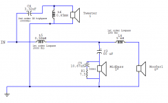
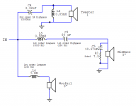
Hi Felix, you need a bandpass filter on the mid to turn it into a three way. That is a high pass filter followed by a low pass filter.
So you would need a 250Hz high pass and a 3000 Hz low pass on the mid, and you would have the mid and the woofer in parallel not series. So yes you do add a highpass in front of the mid... I assume the circuit you posted was the current 2.5 way implementation!
Tony.
So you would need a 250Hz high pass and a 3000 Hz low pass on the mid, and you would have the mid and the woofer in parallel not series. So yes you do add a highpass in front of the mid... I assume the circuit you posted was the current 2.5 way implementation!
Tony.
Last edited:
Cheers Winter,
Calculated online a 1st order highpass at 250HZ to need a 80µf capacitor, can this just be placed before the mid as in the diagram to make it into a bandpass? Or are bandpass filters calculated differently?
If this is the case it can be implemented very easily...
Cheers,
Felix
Calculated online a 1st order highpass at 250HZ to need a 80µf capacitor, can this just be placed before the mid as in the diagram to make it into a bandpass? Or are bandpass filters calculated differently?
If this is the case it can be implemented very easily...
Cheers,
Felix
Attachments
That doesn't look right to me, I think you will get a pretty funky transfer function for the 8" with that (could be wrong as I haven't designed any three way crossovers, just going off what I have seen before and read).
I would say you need to parallel the 8" from the speaker terminals not after the bandpass for the mid.
Since the current implementation is a 2.5way the current filter for the woofer includes the .58 mH coil so it will change a bit if you only have the 5mH on the woofer.
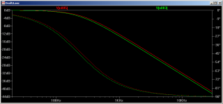
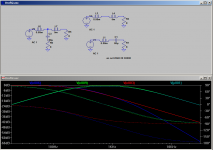
So if you wire the woofer completely separately it should be fine... I just used spice to see the difference with and without the .58mH coil (for a 8 ohm resistive load) it only makes a small difference. Red is with 5mH only.
edit: just attached a second spice sim comparing the two topologies. Not as funky as I thought it might be, but this is only using resistive load, so will almost certainly behave different when a real driver is in the circuit. The Green and red curves are with the woofer and mid circuits separate, the blue and turquoise traces are the topology you posted. But as I said this is spice a with resistive load.
Tony.
I would say you need to parallel the 8" from the speaker terminals not after the bandpass for the mid.
Since the current implementation is a 2.5way the current filter for the woofer includes the .58 mH coil so it will change a bit if you only have the 5mH on the woofer.
So if you wire the woofer completely separately it should be fine... I just used spice to see the difference with and without the .58mH coil (for a 8 ohm resistive load) it only makes a small difference. Red is with 5mH only.
edit: just attached a second spice sim comparing the two topologies. Not as funky as I thought it might be, but this is only using resistive load, so will almost certainly behave different when a real driver is in the circuit. The Green and red curves are with the woofer and mid circuits separate, the blue and turquoise traces are the topology you posted. But as I said this is spice a with resistive load.
Tony.
Attachments
Last edited:
I think I may as well keep them separate, just to be sure! (As that simulation shows, 0.58mh is not much difference!).
Would this then be the correct XO? I can't see that it makes any difference which way around you have the capacitor and inductor in that band pass, but out of curiosity is there a difference in which filter comes first?
Thanks for your help!
Felix
Would this then be the correct XO? I can't see that it makes any difference which way around you have the capacitor and inductor in that band pass, but out of curiosity is there a difference in which filter comes first?
Thanks for your help!
Felix
Attachments
looks good to me ") As far as I know it shouldn't matter whether it is cap - coil or coil - cap. Often it is shown cap-coil but I think that is just because it is more intuitive when viewing the transfer functions ie it ramps up for the cap and ramps down for the coil.
As far as I know it shouldn't matter whether it is cap - coil or coil - cap. Often it is shown cap-coil but I think that is just because it is more intuitive when viewing the transfer functions ie it ramps up for the cap and ramps down for the coil.
for trying out it might be best to just get some bi-polar electros (simply because of cost), though my experience with using bipolars for try-outs hasn't been great (though I was using them in notch filters which may be more finicky than straight in series use).
RS australia have a polypropylene 80uF but it is $46.00 a pop! Partsconnexion in Canada are the best source of cheap high value polypropylene caps that I am aware of. The axon caps they stock are supposed to be quite good (I'm currently using them) and the price is great. AXON True Cap Metallized Polypropylene Capacitors 82uF is $13.82 US. You could add around $10.00 US for shipping via the cheapest method (ie postal which takes a few weeks). You can pay an extra dollar to get them matched as well.
I haven't seen in the thread that you have done any measurements or simming, so I'm guessing you are going with text book values. If that is indeed the case it is probably best not to spend too much money without doing some measurements as results may not be what you expect
edit: I always forget about WES (wagner electronics services) http://www.wagner.net.au/ good place to get 100V bipolars. you could get a 68uF for $1.25 and parallel it with a 12uF film cap to get your 80uF... not sure if this is a good or bad idea though 80uF isn't a value they stock. nearest are 68uF and 100uF. They have generic brand 12uF polyprops for $4.90.
Tony.
As far as I know it shouldn't matter whether it is cap - coil or coil - cap. Often it is shown cap-coil but I think that is just because it is more intuitive when viewing the transfer functions ie it ramps up for the cap and ramps down for the coil. for trying out it might be best to just get some bi-polar electros (simply because of cost), though my experience with using bipolars for try-outs hasn't been great (though I was using them in notch filters which may be more finicky than straight in series use).
RS australia have a polypropylene 80uF but it is $46.00 a pop! Partsconnexion in Canada are the best source of cheap high value polypropylene caps that I am aware of. The axon caps they stock are supposed to be quite good (I'm currently using them) and the price is great. AXON True Cap Metallized Polypropylene Capacitors 82uF is $13.82 US. You could add around $10.00 US for shipping via the cheapest method (ie postal which takes a few weeks). You can pay an extra dollar to get them matched as well.
I haven't seen in the thread that you have done any measurements or simming, so I'm guessing you are going with text book values. If that is indeed the case it is probably best not to spend too much money without doing some measurements as results may not be what you expect
edit: I always forget about WES (wagner electronics services) http://www.wagner.net.au/ good place to get 100V bipolars. you could get a 68uF for $1.25 and parallel it with a 12uF film cap to get your 80uF... not sure if this is a good or bad idea though
80uF isn't a value they stock. nearest are 68uF and 100uF. They have generic brand 12uF polyprops for $4.90. Tony.
Last edited:
Ah k, thanks for that mate!
Speakerbug has 82uF polypropylene for $22.62 each, which may be the go... however, I only got this value of 80uF off an online high pass (250 HZ, 8 ohm [as visaton website graph suggests]) calculator, would this be correct? Any good links for a better (or different) one to confirm?
I haven't done any measuring of actual values of parts yet since I don’t really have the gear (only a good multimeter). I am assuming you would need a CRO? I'm still a student at the moment so I am not really looking to get into it all too much yet, for now I will trust the website
Thanks again for your help!
Felix
Hi Felix,
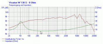
I just had a look at the visaton graph, at 250Hz it looks to me like the impedance is closer to 6 ohms (assuming this is the right graph W 130 S - 8 Ohm - Soundlabs Group) bit hard to tell but I'd say somewhere around 6.2 ohms.
By measurements I mean at a minimum impedance measurements of the drivers mounted in the boxes. Ideally also acoustic (ie freq response) measurements of the drivers in the box as well (as then you can do actual crossover simulations and optimization).
You can do impedance measurements with a decent sound card (any modern motherboard with High definition audio on board will probably be fine) and a jig, I use the walin jig II, but you can also do it using Claudio Negro's cable jig and a freeware program called speakerworkshop. If you want a no hassles solution (getting up to speed with speaker workshop can be a challenge) then the woofer tester 3 is another option. Note that I do not use an amp when doing impedance measurements I do it straight off the sound cards output.
I've attached the graph below that I was looking at and arrowed 250Hz.. the impedance ticks are 2 ohms each...
Tony.
I just had a look at the visaton graph, at 250Hz it looks to me like the impedance is closer to 6 ohms (assuming this is the right graph W 130 S - 8 Ohm - Soundlabs Group) bit hard to tell but I'd say somewhere around 6.2 ohms.
By measurements I mean at a minimum impedance measurements of the drivers mounted in the boxes. Ideally also acoustic (ie freq response) measurements of the drivers in the box as well
(as then you can do actual crossover simulations and optimization). You can do impedance measurements with a decent sound card (any modern motherboard with High definition audio on board will probably be fine) and a jig, I use the walin jig II, but you can also do it using Claudio Negro's cable jig and a freeware program called speakerworkshop. If you want a no hassles solution (getting up to speed with speaker workshop can be a challenge) then the woofer tester 3 is another option. Note that I do not use an amp when doing impedance measurements I do it straight off the sound cards output.
I've attached the graph below that I was looking at and arrowed 250Hz.. the impedance ticks are 2 ohms each...
Tony.
Attachments
Oh wow, turns out I can't read a graph properly! (Yep I took those spaces as 1 ohm each - My bad).
I'll have a look into measurements, however my laptop only has a stock soundcard, and the output died a month or two ago (but works randomly every now and then...), so I may have to get set up on some different gear.
However since I have already made the boxes and pretty much the XO, I am only really looking for a small tweak to it to drop those low frequencies from the midrange!
Does that calculation of 80uF sound about right? It's a lot higher than the other HP filter, however at a much lower frequency and I understand that they would not be in a linear relationship...
Any good website with a good band pass calculator? Or seeing as I already have the 0.58mH inductor as a LP can I just add in a calculated HP in series and call it a band pass (As I have done in the last diagram? IE: an 80uF?).
Thanks once again!
Felix
- My bad).I'll have a look into measurements, however my laptop only has a stock soundcard, and the output died a month or two ago (but works randomly every now and then...), so I may have to get set up on some different gear.
However since I have already made the boxes and pretty much the XO, I am only really looking for a small tweak to it to drop those low frequencies from the midrange!
Does that calculation of 80uF sound about right? It's a lot higher than the other HP filter, however at a much lower frequency and I understand that they would not be in a linear relationship...
Any good website with a good band pass calculator? Or seeing as I already have the 0.58mH inductor as a LP can I just add in a calculated HP in series and call it a band pass (As I have done in the last diagram? IE: an 80uF?).
Thanks once again!
Felix
Hi Felix,
I've used this one Crossover Design Chart and Inductance vs. Frequency Calculator(Low-pass) for getting values for transformation into my active filter project. I tried a few and it seemed to be better than some.
I just plugged in 250 Hz and 8 ohms and it said 79.5 uF (pretty close to your figure of 80uF so I guess the calculator you used was ok when I put in 6.2ohms it comes out at 102.5 uF 6.4 ohms is 99.3uF so I reckon 100uF is probably about right.
I suspect that you couldn't use speakerworkshop to do impedance measurements with a laptops built in sound. You need a line in. Purchase of a good quality USB sound card could probably be necessary, sorry I was assuming use of a desktop computer!
Tony.
I've used this one Crossover Design Chart and Inductance vs. Frequency Calculator(Low-pass) for getting values for transformation into my active filter project. I tried a few and it seemed to be better than some.
I just plugged in 250 Hz and 8 ohms and it said 79.5 uF (pretty close to your figure of 80uF so I guess the calculator you used was ok
when I put in 6.2ohms it comes out at 102.5 uF 6.4 ohms is 99.3uF so I reckon 100uF is probably about right. I suspect that you couldn't use speakerworkshop to do impedance measurements with a laptops built in sound. You need a line in. Purchase of a good quality USB sound card could probably be necessary, sorry I was assuming use of a desktop computer!
Tony.
Thanks for that!, Have done quite a bit of searching and haven't found a calculator (or page) as good as that!
I reckon I will go with a 100uF then, and see how it sounds! If not I will revert back to the 2.5 way and be done with it (I am happy in either case!)
Thanks for your help mate, ill give an update when done!
Cheers,
Felix
I reckon I will go with a 100uF then, and see how it sounds! If not I will revert back to the 2.5 way and be done with it (I am happy in either case!)
Thanks for your help mate, ill give an update when done!
Cheers,
Felix
No problem Felix speaker bug has 100uF caps too, and $28 a pop is a lot cheaper than you will get anywhere else in Aus that I have seen I'd forgotten about them, had thought about getting some of the jantzen coils from them (till I decided I needed some obscure values that I should wind myself and still haven't bought the wire...)
Hope it works out well, and if it doesn't it is all part of the learning experience I spent a small fortune on "stock" crossovers and different drivers from jaycar during my Uni years, You are streets ahead by making your own crossovers even if you are just taking into consideration the actual driver impedance (and using a zobel) compared to me back then. I had no idea and just bought pre-built crossovers (and drivers that really weren't that suitable to work together).
Tony.
speaker bug has 100uF caps too, and $28 a pop is a lot cheaper than you will get anywhere else in Aus that I have seen I'd forgotten about them, had thought about getting some of the jantzen coils from them (till I decided I needed some obscure values that I should wind myself and still haven't bought the wire...) Hope it works out well, and if it doesn't it is all part of the learning experience
I spent a small fortune on "stock" crossovers and different drivers from jaycar during my Uni years, You are streets ahead by making your own crossovers even if you are just taking into consideration the actual driver impedance (and using a zobel) compared to me back then. I had no idea and just bought pre-built crossovers (and drivers that really weren't that suitable to work together). Tony.
- Status
- This old topic is closed. If you want to reopen this topic, contact a moderator using the "Report Post" button.
- Home
- Loudspeakers
- Multi-Way
- Building new speakers!