You are not the first (and probably not the last) to notice that peculiarity:Interestingly, when I mute the source and stick my ear into the speaker I can hear nothing. This amp is really silent")
https://www.diyaudio.com/community/...-the-circlophone-topology.205225/post-2876352
Hi there!
I started to populate the boards Mr. Pronk designed and kindly sent the gerbers to fabricate, sourcing the last things i need atm.
I'm trying to make a cheap soft recovery bridge rectifier (to avoid potential snubbering experimentation) but i'm a little stuck guessing its current demand.
I did a sim assuming the psu will "see" 6*speaker impedance as load (that popped up somewhere in this forum a while ago) and 10000uf reservoir caps.
This yielded 1.3 A average and 4.8 A RMS per diode.
Datasheets says: "maximum average forward rectified current". If that is what i get when i make ctrl + left click in LTspice into diode current plot, then 4 UF5408 (3A) may be enough @4ohm. HER508 which may be soft (5A) is the other i can source cheaply. Also 6a6 (6a) and sr5200 (5a) but not sure if those are soft.
Assuming my sim may be fundamentally flawed, which is the recomended rating for each diode in a diy bridge?
Psu parts i already have:
220/18-0-18 5 amp trafo. C (6800uf) - R (5 or 6, 2.2 ohm // resistors) - C (6800uF).
Sidenote: i'm going to try TTA004B as driver as VAS will be TTC004B.
Gosh, There is even a MOSFET version nowdays .
.
Best regards!
I started to populate the boards Mr. Pronk designed and kindly sent the gerbers to fabricate, sourcing the last things i need atm.
I'm trying to make a cheap soft recovery bridge rectifier (to avoid potential snubbering experimentation) but i'm a little stuck guessing its current demand.
I did a sim assuming the psu will "see" 6*speaker impedance as load (that popped up somewhere in this forum a while ago) and 10000uf reservoir caps.
This yielded 1.3 A average and 4.8 A RMS per diode.
Datasheets says: "maximum average forward rectified current". If that is what i get when i make ctrl + left click in LTspice into diode current plot, then 4 UF5408 (3A) may be enough @4ohm. HER508 which may be soft (5A) is the other i can source cheaply. Also 6a6 (6a) and sr5200 (5a) but not sure if those are soft.
Assuming my sim may be fundamentally flawed, which is the recomended rating for each diode in a diy bridge?
Psu parts i already have:
220/18-0-18 5 amp trafo. C (6800uf) - R (5 or 6, 2.2 ohm // resistors) - C (6800uF).
Sidenote: i'm going to try TTA004B as driver as VAS will be TTC004B.
Gosh, There is even a MOSFET version nowdays
.Best regards!
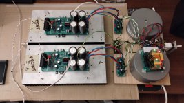
And another Circlophone is alive!
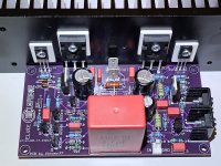
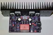
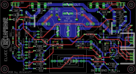
I made my own PCBs. The sources (Eagle) and the PCB fabrication files are attached here, in case they might be useful for the community.
R21 is made of two series resistors on the PCB, which makes it easier to get the necessary value, depending on the supply voltage.
I used MJW21194 power transistors, BD140-16 drivers, and TTC004B VAS.
It's a pretty good amp - it sounds clear, fast, good details, powerful and tight bass. When I first turned it on, I found the treble to be on the harsh side - but, surprisingly, it got better after a couple of days. So it needs some burn-in time before giving its best.
It is powered from a pair of simple cap multiplier PSUs, +/-21VDC. It draws 21W from the mains when idle. The heatsinks barely get warm. It's completely silent with the input shorted. DC offset is negligible (0.7mV).
I think I will keep it for daily listening while working on the computer, and the next step is to make an enclosure for it.
Attachments
The left channel on my working Circlophone has malfunctioned. There is no discernible bias current in the output stage, the heat sink is cool.
Here's what I could measure:
input shorted, speaker out open
V+ = 27.7V
V- = 27.7V
I(R21) = 1.515 mA, R21 = 33K
There is no voltage drop across R8, R11, R24
Q5 collector = 0V
Q6 collector = 3.4V
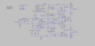
Attached is my circuit as built, and the numbering should match Elvee's original schematic.
Please let me know how to go about debugging this.
Thanks
Here's what I could measure:
input shorted, speaker out open
V+ = 27.7V
V- = 27.7V
I(R21) = 1.515 mA, R21 = 33K
There is no voltage drop across R8, R11, R24
Q5 collector = 0V
Q6 collector = 3.4V
Attached is my circuit as built, and the numbering should match Elvee's original schematic.
Please let me know how to go about debugging this.
Thanks
Attachments
some more measurements:
Ve(Q1) = 27.5
Vb(Q1) = 27.5
Vc(Q1) = 0
Ve(Q2) = 27.5
Vb(Q2) = 27.5
Vc(Q2) = 27.5
When not powered, R4 measures zero. Isn't it weird?
Can this happen when Q2 is shorted between the collector and emitter? Simulation seems to agree with measurements.
Ve(Q1) = 27.5
Vb(Q1) = 27.5
Vc(Q1) = 0
Ve(Q2) = 27.5
Vb(Q2) = 27.5
Vc(Q2) = 27.5
When not powered, R4 measures zero. Isn't it weird?
Can this happen when Q2 is shorted between the collector and emitter? Simulation seems to agree with measurements.
Last edited:
- Home
- Amplifiers
- Solid State
- Building Elvee's Circlophone: Documentation, Parts, Accessories, & beginner friendly