Building an ultimate low power class A amplifier – my way
After realizing that loud listening with my equipment and listening conditions, requires 1 W average at most, I started contemplating my own design of a suitable low power amplifier that could be considered as close to perfect as it gets.
This is short list of requirements taken in the account during design:
Objective
Audiophoolery or not really essential
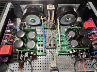
Last summer I started with OS evaluation and settled on the diamond buffer with BJT CFP output. Circuit variations were assembled on the breadboards and careful listening and measurements were performed. It was very good but not good enough. Switch to lateral MOSFETs was done, as they provide low distortion, thermal stability and monotonic steeply falling distortion harmonic profile. After satisfactory results, my preferred operational amplifier was added as a VAS stage to make amplifier circuit complete. After much more listening and measurements, final evaluation build was assembled on the PCB and listened to and measured again. All good, followed with required parts order and a lot of assembly work. Final measured results are here:
Frequency response DC to 1.3 MHz
Max. power 10W/8Ω, 20W/4Ω
Distortion:
Damping factor 945/8Ω, flat line from 20 Hz to 20 kHz
Slew rate 86 V/us for a +- 12.5V swing (290 ns rise time)
DC offset less than 400 uV
Sound
Everything I declared as a goal and much more. Yes, there are reproduction details never heard before and soundstage was never that wide, deep and detailed.
EDIT:
PCB fabrication gerber files added.
10/10/23 Mouser BOM added
17/10/23 correct DC offset value. Previous measurement had preamplifier DC offset included.
Added result of 32 tone test at post #54
After realizing that loud listening with my equipment and listening conditions, requires 1 W average at most, I started contemplating my own design of a suitable low power amplifier that could be considered as close to perfect as it gets.
This is short list of requirements taken in the account during design:
Objective
- Extremely low distortion (single digit ppm) up to full power of 10W/8Ω or 10W/4Ω
- Monotonic harmonic profile with high order harmonics at very low levels
- High slew rate
- Soft clipping
- Thermal stability
- Stable operation with any capacitive load
- High damping factor
- Negligible DC offset
- Very high EMI immunity by use of Zero Signal Planes
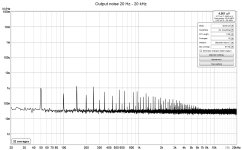
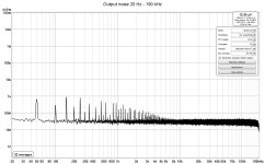
- Low output noise
- Clean and very detailed sound with no specific coloration
- Wide and deep soundstage absolutely detached from the loudspeakers (they simply must ‘not exist’)
- Very enjoyable sound reproduction, with no harshness but sound must be very transient with no ‘dullness’
- Whole day listening must not produce any listening fatigue, rather you ask for more
Audiophoolery or not really essential
- No capacitors in the direct signal path
- Dual mono power supplies
- Very wide power bandwidth
- Regulated power supplies with excellent PSRR, transient response and noise
Last summer I started with OS evaluation and settled on the diamond buffer with BJT CFP output. Circuit variations were assembled on the breadboards and careful listening and measurements were performed. It was very good but not good enough. Switch to lateral MOSFETs was done, as they provide low distortion, thermal stability and monotonic steeply falling distortion harmonic profile. After satisfactory results, my preferred operational amplifier was added as a VAS stage to make amplifier circuit complete. After much more listening and measurements, final evaluation build was assembled on the PCB and listened to and measured again. All good, followed with required parts order and a lot of assembly work. Final measured results are here:
Frequency response DC to 1.3 MHz
Max. power 10W/8Ω, 20W/4Ω
Distortion:
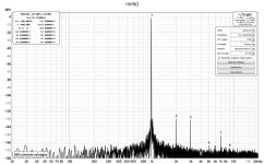
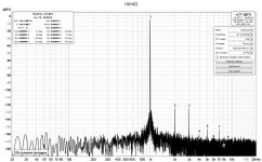
- 1W/8Ω 0.00005% -126 dBc
- 8W/8Ω 0.00021 -113.5 dBc
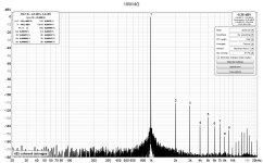
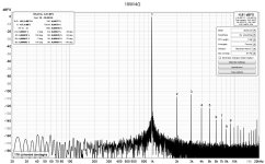
- 10W/8Ω 0.00024% -112 dBc
- 1W/4Ω 0.000074 -122.6 dBc
- 10W/4Ω 0.00035 -109.2 dBc
- 16W/4Ω 0.0011% -99.5 dBc
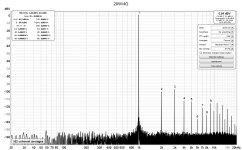
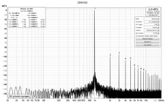
- 20W/4Ω 0.0016% -96 dBc
Damping factor 945/8Ω, flat line from 20 Hz to 20 kHz
Slew rate 86 V/us for a +- 12.5V swing (290 ns rise time)
DC offset less than 400 uV
Sound
Everything I declared as a goal and much more. Yes, there are reproduction details never heard before and soundstage was never that wide, deep and detailed.
EDIT:
PCB fabrication gerber files added.
10/10/23 Mouser BOM added
17/10/23 correct DC offset value. Previous measurement had preamplifier DC offset included.
Added result of 32 tone test at post #54
Attachments
Last edited:
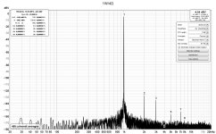
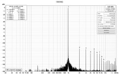
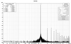
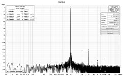
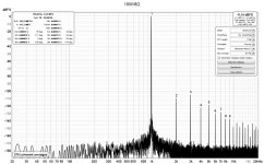
Distortion
At several watt levels, this amplifier has only very low H2 + H3 and all higher order harmonics are some 30 dB down. Low distortion is maintained up to the clipping level.
At several watt levels, this amplifier has only very low H2 + H3 and all higher order harmonics are some 30 dB down. Low distortion is maintained up to the clipping level.
Attachments

I’ve found a bug in REW software distortion measurement, that has gone unnoticed by all for a whole year after last official release. So, my distortion measurements are not correct for several dB. 
Nothing major but previous numbers look nicer. Here are correct numbers (measured, checked and rechecked again, several times over).
Nothing major but previous numbers look nicer. Here are correct numbers (measured, checked and rechecked again, several times over).
- 1W/8Ω 0.00009% -121 dBc
- 10W/8Ω 0.00065% -103.7 dBc
- 1W/4Ω 0.00013 -117 dBc
- 10W/4Ω 0.00077% -102.3 dBc
- 16W/4Ω 0.0014% -96.9 dBc
- 20W/4Ω 0.002% -94 dBc
Attachments
Mostly for chance to use preamplifier without any unnecessary signal attenuation.Mostly there would be no problems but it depends on how much you’d like to reduce gain. This amplifier has low gain of 4x or 12 dB, as it is a low power one. So, what would be a reason for further reducing gain?
Gain could be reduced to 2x or 6dB. That requires NFB network values and compensation capacitor changes. Lower gain is out of question due reduced stability.
However, your preamplifier will work at high output voltages (4.5 Vrms required for full power) and will certainly have 20 – 40 dB higher distortion than amplifier it drives.
However, your preamplifier will work at high output voltages (4.5 Vrms required for full power) and will certainly have 20 – 40 dB higher distortion than amplifier it drives.
I’ve attached to first post gerber files. Format is as required by JLCPCB, where I have ordered mine, but is likely OK for most PCB production services. If ordering, check option “Specify Layer Sequence” and set values as on this picture. As this is 4-layer PCB, price is unfortunately higher. If needed, I can later add BOM in Excel format.

It’s sufficient. Bias current can be adjusted from 0.7 to 1.4 A and target is 1 A. That’s the bias at which all measurements were taken. If intended loudspeakers impedance is mostly 8Ω (don’t relay on manufacturer specs, rather some magazine measurements) 0.8 A is enough. For 4Ω, stick with 1 – 1.2 A. As there is no resistor in the rails for current measurement, I’ll provide corresponding voltages for various bias currents, measured at R16 or R17.
Yes, +/- 17 V is target supply voltage. It can't be higher than some +/- 18.5 V due the opamp in front.What is the recommended power supply voltage? Am I correct in assuming you are you using +/-17.5 VDC?
- Home
- Amplifiers
- Solid State
- Building an ultimate low power class A amplifier – my way