You simply got 2V leds. Positive is supposed to drop more. Take negative as a measure. Listen to it first. I liked it under 11V more but maybe you will like it all well as it is.
I swaped 2 of the LEDs to some spare yellow ones I had with less drop. Getting 11.36 from 11.81. 5mm though. Will get more next week to replace.
Since negative is -10.56, I can just leave it there right? No issues with the rest of the 2V LEDs right?
cheap LEDs to get the correct voltage
Marlin P Jones has 100 red LEDs for $1.95 here: 3mm RED LED Pack of 100-MPJA, Inc.
they're listed as 1.8v nominal, but all the ones I've checked are in the 1.72 to 1.74 range. Pair them with a few 1.9s to get 1.8. I used them and am getting +10.3 and -9.5 rails, with 2.1mv and 0.5mv DC offset.
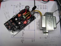
Also, Radio Shack has a relatively cheap ($10.50) transformer that's perfect for this project: 25.2VCT (12.6 - 0 - 12.6) @ 2A.
Marlin P Jones has 100 red LEDs for $1.95 here: 3mm RED LED Pack of 100-MPJA, Inc.
they're listed as 1.8v nominal, but all the ones I've checked are in the 1.72 to 1.74 range. Pair them with a few 1.9s to get 1.8. I used them and am getting +10.3 and -9.5 rails, with 2.1mv and 0.5mv DC offset.
Also, Radio Shack has a relatively cheap ($10.50) transformer that's perfect for this project: 25.2VCT (12.6 - 0 - 12.6) @ 2A.
Attachments
Marlin P Jones has 100 red LEDs for $1.95 here: 3mm RED LED Pack of 100-MPJA, Inc.
they're listed as 1.8v nominal, but all the ones I've checked are in the 1.72 to 1.74 range. Pair them with a few 1.9s to get 1.8. I used them and am getting +10.3 and -9.5 rails, with 2.1mv and 0.5mv DC offset.
Also, Radio Shack has a relatively cheap ($10.50) transformer that's perfect for this project: 25.2VCT (12.6 - 0 - 12.6) @ 2A.
Good cheap choices and to the target. Especially the Tx. Those axial caps behind the triple connector that shunt the Vrefs are the at the most influential position subjectively. What are they? Did you put the buffer in service yet?
I have the same transformer. Wait for buzz and heat. It has issues.
Shame, at 12.6-0-12.6 is optimum. Is it having issues consistently? Or its just highly probable?
what kinda buzz?
Do you mean physical, mechanical noise or electrical sounds you hear through the speakers?
Mine does not make any perceivable mechanical noise so far. It gets **slightly** warm, a little over room temp -- I'd estimate maybe 85 deg. F. No big deal, but I will keep an eye on it. Had it running for a couple of days already.
Have not hooked it up to speakers yet.
")
Good cheap choices and to the target. Especially the Tx. Those axial caps behind the triple connector that shunt the Vrefs are the at the most influential position subjectively. What are they? Did you put the buffer in service yet?
I didn't realize that's the most critical spot. They're nothing special, I've had them in my parts bin for years. Panasonic GE series, 105 deg. C rating; 100Uf/25v. If I'm not happy with the sound I'll replace them with something better. Still in the middle of putting all the bits together, and waiting for LDRs.
circuit board warning
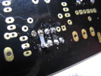
I don't mean this as negative, but there are issues with these boards:
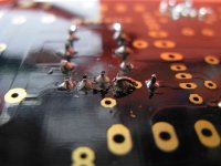
1) It's all too easy for the traces to lift off in both LED strings, especially the 5. It happened to me twice, see the pix. Be careful when you cut the excess leads!
2) Why aren't the pads tin plated? It's much more difficult to solder to un-tinned pads. (I use Wonder solder & a temp controlled station; it's not my equipment).
3) Black solder mask...the WORST choice for real-world checking of pads & traces. You can't see through the board! It may look "cool", but it's a builder's nightmare.
I don't mean this as negative, but there are issues with these boards:
1) It's all too easy for the traces to lift off in both LED strings, especially the 5. It happened to me twice, see the pix. Be careful when you cut the excess leads!
2) Why aren't the pads tin plated? It's much more difficult to solder to un-tinned pads. (I use Wonder solder & a temp controlled station; it's not my equipment).
3) Black solder mask...the WORST choice for real-world checking of pads & traces. You can't see through the board! It may look "cool", but it's a builder's nightmare.
Attachments
I can't recall the specification, but the DCB1 pcbs look like they are gold flashed.2) Why aren't the pads tin plated? It's much more difficult to solder to un-tinned pads.
I found them very easy to wet with solder.
I have done a little component removal and re-soldering and none of the pads lifted (yet).
Yep, I thought that my snips might be a factor...but they're almost new. I got smaller ones that cut a little cleaner. These areas are sensitive to "torquing" when they're cut. I'm just saying...be aware of that when cutting.
I found it harder to solder to these "gold" pads...I think the combination of having to apply heat longer in these areas of very short traces, makes them more susceptible to lift off when you cut.
These are the only boards I've ever had this happen when soldering to the first time (aside from multiple remove/re-solder situations).
I found the same, quite easy to solder despite some of the pads are a bit close. Have not desoldered almost anything though.I can't recall the specification, but the DCB1 pcbs look like they are gold flashed.
I found them very easy to wet with solder.
I have done a little component removal and re-soldering and none of the pads lifted (yet).
I am learning from CRT that they have run a 17 builds tube vs solid preamps BLIND panel test in Indonesia and they have ranked the DCB1 in top 3rd among tube and SS builds with gain, not buffers, and over 4 times its cost. That was in the ''Solfegio'' forum.
Auto translation:
''Specifically for B1 and Salas SF, I think Price / Performancenya very promising with a cost of less than 1 / 4 (a quarter) the other champions, he was able to show dozens performancenya outperformed other systems, thus Buffer B1 is worth if it is considered Salas Project DIY a very decent build.''
http://img14.imageshack.us/img14/5713/b1salaskprambutan.jpg
Hey, this one does not even have an LSPD or a switcher...What is that, extra filter caps with long cabling? Could have been done and do better.
Well done Salas!

Thanks to CRT and TeaBag.
- Home
- Amplifiers
- Pass Labs
- Building a symmetrical PSU B1 buffer