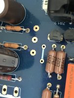
No jumper strictly required between those two points linked with the stripe.Only as a reinforcement. A remnant from when the board was single layer. You can confirm with continuity buzzer of a DMM.
Three pads are +/0/- reg out points either for testing the PSU is well or for powering something peripheral.
Three pads are +/0/- reg out points either for testing the PSU is well or for powering something peripheral.
I'm not seeing where the PSU side attaches to earth ground -or through a CL-60 to ground?
Using an Antek AS-0515 - 50VA 15V
Which terminals to attach which wires?
Both primaries and both secondaries must be used to get the 50VA?
Ignore the piece of tape with what appears to be CT on it.
Thanks again.
Using an Antek AS-0515 - 50VA 15V
Which terminals to attach which wires?
Both primaries and both secondaries must be used to get the 50VA?
Ignore the piece of tape with what appears to be CT on it.
Thanks again.
Attachments
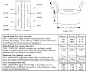
Red with red, black with black for 115V primary configuration. Outer green outer blue to AC input connector's outer screws. Middle green and blue to same center screw. Purple is the static screen's drain wire, goes to mains earth.
You may use the middle screw's pad underneath, or the unused jumper pad next to it, to solder a chassis return cable through a CL-60.
You may use the middle screw's pad underneath, or the unused jumper pad next to it, to solder a chassis return cable through a CL-60.
With 122V at the wall, I'm getting 9.60V and 9.65V after warmup on the test pads.
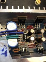
Had to source some parts from eBay. Had to guess at a sub for the little automotive cap. Mosfets were recycled - one IRFP240 runs a few degrees cooler than the rest. All running around human body temperature. Approximately doubled the value of the resistor for the front panel LED.
I'm reading 0.00V DC on the output. Using four back panel inputs, one front and not using #6, wires are coiled up and tied off out of sight.
Only so much patience for working with the coax used for the pot and output, hoping the braided input wires are quiet.
Going to let it warm for a few hours tonight, then recheck and give it a test tomorrow.
Attachments
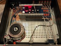
The heatsinks did not have a smooth mounting surface, with the two of them placed against each other light could be seen between them. Possible cause, not sure if testing VDS is as simple as testing the leads while powered on.
I left it on overnight, and left it on for ~20 hours while mosfet temps evened out a little, three were at 100F, one at 97F. Tried hooking it up to a cheap amp / speaker, no sound. The first thing I tested was the switch - accidentally tested the wrong points and had an intermittent beeping for continuity. I had ruined the switch with too much heat, pushing that terminal back into the switch and creating a short. Removed the switch and tried connecting the pair the switch should have been making, still no sound.
I've put it away for the day.
VDS is DC voltage between Mosfet pins 2,3. But a bit uneven mounting surface seems to be the main explanation. The switch provides ground path to the next input relay's coil with each step, so it can energize and click to engage the corresponding signal input. Also check if the output delay relay works correctly. Let us know if you eventually debugged the relays system or how we can help.
Trying to narrow down how to troubleshoot. I immediately bypassed the rotary switch and that didn't make a difference, but I only tested one input relay.
The little film capacitor R82DC3100AA50J I don't remember polarity markings, both had square pads on the PCB.
The C517 was specifically advertised on eBay as Darlington.
The C550's were the most suspect part as far as handling goes before opening the package. They looked a little rough for wear. Another part sourced from eBay.
2SK170's came from a trusted source should be at 8mA IDSS.
I used a clip on heatsink on the top side of the board which clipped onto a lead to minimize any excessive heat reaching any of the sensitive parts. It slows down assembly time in that I have to flip the board over and re-clip for each lead.
The jumper for using 12V relays to bypass the 2x 220 resistors. I assumed they were in parallel, so only used one jumper and put it on the pair of pads under the pair which are labeled as "note".
Any way to solder wires to any particular pads to bypass the output relay to test? Other suggestions welcome.
Removing the relay would require a third soldering iron and be destructive, not something I would look forward to. I have spares, but hoping to avoid that.
C550's emitter in the delay circuit is at same node with the 47k 100uF RC timer parts meeting point. When all is well the 7812 should provide about 12V, the C550 emitter point should climb for few seconds ending up with 9-10V to kick the C517's base open so to pull current through the collector and energize the relay's coil. 12V rail and C517 Darlington give 11.3V across the coil and its flyback diode in parallel.
If you have doubts about the particular C517, a C550 should also work in its place. Due to less Vbe the coil gets 11.8V across. C550 was in the prototype circuit the driver transistor as well but C517 was adopted to solve few relay mechanical chatter oscillation incidents reported far back in time. C550 needed a 0.1uF ceramic C to B underside if that happened. If the ebay sourced transistors are fake all funny things can happen.
If you have doubts about the particular C517, a C550 should also work in its place. Due to less Vbe the coil gets 11.8V across. C550 was in the prototype circuit the driver transistor as well but C517 was adopted to solve few relay mechanical chatter oscillation incidents reported far back in time. C550 needed a 0.1uF ceramic C to B underside if that happened. If the ebay sourced transistors are fake all funny things can happen.
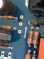
Any way to solder wires to any particular pads to bypass the output relay to test?
You normally find output signal entering the relay where I point in your picture for each channel, but I believe your signal input selection relay does not work right now as well. Because it shares the same LM7812's output rail. You can check that by measuring across input relay's flyback diode.
Attachments
could a LED resistor 2x the value in the BOM pull it down? I can't remember what I selected, just knew I wanted a very, very dim led for front panel.
I'm getting 12V across the input relay, 5.15 across the output. I can't see a couple of the cheap resistors under the LM7812. That's the only thing reasonable?
I'm getting 12V across the input relay, 5.15 across the output. I can't see a couple of the cheap resistors under the LM7812. That's the only thing reasonable?
Last edited:
- Home
- Amplifiers
- Pass Labs
- Building a symmetrical PSU B1 buffer