Please note that I'm use cheap source that built in volume & remote control so I don't use 20k pot (but I already order it).
So next time I must use better setup& get ready for another better story
20K pot roof value is a must. Try one of those cheap switchers with smd resistors on ebay at least.
If you don't mind the reduced rise time on a square wave test with a fast generator that I could also hear as less resolution with 50K and 100K pots when I was developing it, then yes there are no ill side effects in DCB1's operation. 20-25K tops is what I recommend for no compromise in SQ. The Ciss characteristic of the 2SK170 is certainly high enough in pF to curtail the response and rise time when married with more series input impedance than strictly necessary in a system. Not enough to render those characteristics inadequate, but to compromise what they can be best. It depends on the ancillaries closed loop response too of course.
For me it had an impact in the general replay program's fine HF details too and I can't recommend else than I consider best, explaining my reasons for anybody to weigh in his own system concept of course.
The one I made was without pot and only the 220 kohm resistors. That could explain something. Normally high input impedance = more noise.
20K is 18nVrtHz at 20C. 220K is 60nVrtHz. I don't know the resolution, gain, and most importantly the bandwidth of your power amp so to translate that over a band, but you could try reducing those resistors to less but still comfortable value for your source and verify if you can pick something by ear too.
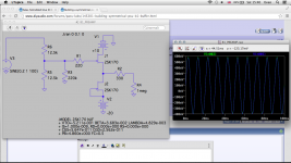
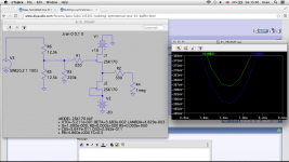
This is how it should measure for 100kHz square wave and 20K pot for your reference.
This is how it should measure for 100kHz square wave and 20K pot for your reference.
20K is 18nVrtHz at 20C. 220K is 60nVrtHz. I don't know the resolution, gain, and most importantly the bandwidth of your power amp so to translate that over a band, but you could try reducing those resistors to less but still comfortable value for your source and verify if you can pick something by ear too.
This is how it should measure for 100kHz square wave and 20K pot for your reference.
The buffer looks into a 25 kohm pot in a Balanced Bride Off Zen, a fantastic pre in our version.
The only reason we made the buffer was a Audio Note dac with 0,47 uf silver in oil caps.
Maybee I could reduce to 100 kohm.
The 20k pot will arrived soon, I'm also planning smd resistor & relay or LSA20K pot roof value is a must. Try one of those cheap switchers with smd resistors on ebay at least.
Ok, will try it ...Try different capacitors for your 5 LEDs filter too. 100uF lytics brands and types for minimum noise but different tone or film caps for more noise (but indifferent at line level for most users) and more BW.
Maybe I will build another one tooGoing to make another one and compare
here's the layout...
Attachments
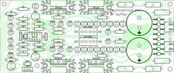
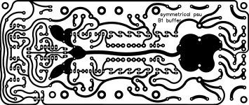
Nice if you want to build too...Nice artwork
it was curved so it's look like my hand drawing one
I also have an ordinary version with no curve
Making the B1 with symmetrical ( +/-) supplies makes it possible to go capless or DC-coupled with the B1.
1. By trimming the supplies a bit non symmetric, the output offset falls to either zero or under half mV, steady. It counteracts naturally non perfectly alike JFET pairs.
I know I am coming to this waaaay late but please bear with me.
I have a couple of questions about how this circuit works. I have simulated the whole thing in ltspice. No matter how much I trim the positive and negative supplies I can never completely eliminate the dc offset. With +10V / -20V I can only get up to 15mV off the original 100mV injected dc offset so it's not really going to work unless there is a decoupling capacitor downstream.
Is this a limitation of the simulation software perhaps?
Also I've not seen any trimmers on GB boards to adjust B+/B- to remove the dc offset. On the contrary the shunt regs match B+/B- very closely indeed.
I can understand the benefit of ditching 2 caps over the original B1, but from my simulation I show that at least 1 cap is still required. That is still minus 1 cap per channel but one can't rely on supply trimming to remove say a 100mV offset.
Am I missing the point somewhere?
PS: Could the same trimming functionality be achieved on the original B1 by replacing one or either of the R2 R3 10k voltage divider resistors with trimmers?
Attachments
Last edited:
The real dcb1 gives +/-1mV dc offset quite often in reported builds here with just good idss matching of the signal jfets. Because I had an LM317&337 original test bed with trimmers for evaluating the signal circuit, moving the supplies a little had a measurable impact on dc offset. I had a picture of it with 0V in yr 2008 by trimming the supplies. Staying put on same afternoon temperature at least. It is somewhere in the original B1 thread, if I will find it I will re-post it here. Don't ask too much from this kind of spice jfet models in general, they are just rough and ready.
Indeed. I thought it might be a limitation of the spice model too. If you've tried and tested it then that's good enough evidence for me that the supply trimming does indeed do the trick
What's the best way to incorporate some trimming functionality on your shunt regs?

You could botch a 500R rheostat instead of an LED per side. Its not productive though, the offset is already very low. If you don't mind that and you wanna do it out of curiosity, its up to you.
- Home
- Amplifiers
- Pass Labs
- Building a symmetrical PSU B1 buffer