I've a funny feeling that I'm going to need another transformer.
My B1 used a 30VA 9-0-9 (connected as a single 18V) supply to the regulator.
Will 9-0-9 be sufficient for the DCB1. 9VAC = 12.7VDC.
I have a feeling that I may need a 12-0-12V transformer.
No, 15-0-15 is best. Use 50VA to be on the rich side also at those currents here.
You need to modify the output relay for grounding at rest position too.
I'll incorporate that one too.
I'm aiming for the Hot-Rod but I did try the Pumkins and they were a nightmare.
Having said that, the guy that I sold them to said they worked perfectly????
Nowt stranger than the oscilloscope.
I saw perfect 20MHz oscillators and the heat was showing they were oscillating. He did nothing and said they were perfect.
Having said that, the guy that I sold them to said they worked perfectly????
Nowt stranger than the oscilloscope.
I saw perfect 20MHz oscillators and the heat was showing they were oscillating. He did nothing and said they were perfect.
Don't know, never saw a Pumpkin in the flesh. DCB1 has been working in hot to very hot builds for too many and too long to give me any worry it will fail on you. Making your own PCB and configuration layout will be the only new factor and its up to you to make it a success. Wishing best of luck.
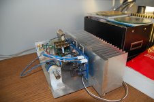
Katie and Dad. I mounted my IRF's under the board. I'll post a pic. It is very convenient. I am currently running mine at 1A. but will drop it back to 600 when i go dual mono. 600mA not as good as 1A, but i feel kinda guilty and i needed a heatsink for my house meter when i trun on all my Pass stuff. Boards are populated for dual mono, but I am busy with another pre at the moment. I am only using 12V secondaries and this helps with dissiaption, but i think some like the idea of more headroom suggesting 15. Using cheapo Radio shack trafo, BTw. I will couple the current B1 with a mesmerize for the dual mono option allowing for two psu's plus dual balnced input as well as one SE.
Here ya go. Like i said very convenient layout that Salas made. Also, the wire you see is Mogami neglex. Very high quality wire for very little money. OFCC and all that stuff. Stranded vs solid, but can't say i can hear the difference. I will try with dual mono with one side being solid and other stranded. Easiest way to compare.
Attachments
Hmm, I see you have mounting space for exotica even.")
High Quality Audio & Industrial Attenuators
http://www.khozmo.com/products_smd.html
High Quality Audio & Industrial Attenuators
http://www.khozmo.com/products_smd.html
I'm "the guy" with KatieandDad's Pumpkin. As mentioned, I'm not seeing any oscillation with either board. My 100Mhz Tektronix should easily lock onto a strong oscillation using the autoset feature. Heatsink runs at ~42C measured with a Fluke 51 thermometer (out in the open on a bench). TO-92 heat seems normal. Output signal looks good. Rolls off way up high (~300 khz) as expected. I've drilled/tapped all heatsinks to mount them securely to the pcb's. Remounted all 'fets to minimize lead length. Cleaned off all residual flux. First Shunty looks good, but did find a short between the top and bottom ground planes that really wasn't a big deal. About to start the second. Sorry for the off topic...
It is hard to spend that kind of dough on attenuator. Plus, I may beginning an affair with a new tube pre that just moved to town. Have you heard said attenuators and have comparison to standard steeped attenuator like my Valab. I was going to try ldr next.
They give 48 steps is their main advantage, and excellent mechanics. Beyond that their sound quality is down to resistor models used. Even better sonics give the 26 steps autoformer pots from Sowter or others. Those additionally need a 27 steps quality switch (27th for ground mute). Intact Audio has a 16 steps one (14+straight in & ground switching) that is the most economic I think as far as autoformers go.
Hmm, I see you have mounting space for exotica even.
High Quality Audio & Industrial Attenuators
High Quality Audio & Industrial Attenuators
Would you go for the 10 or 25 K? 10 I guess?
/Staffan
Here ya go. Like i said very convenient layout that Salas made. Also, the wire you see is Mogami neglex. Very high quality wire for very little money. OFCC and all that stuff. Stranded vs solid, but can't say i can hear the difference. I will try with dual mono with one side being solid and other stranded. Easiest way to compare.
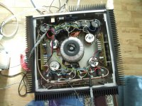
Just looking at your build.
Did it really need a heatsink that size ?
I'll be using a 20-0-20 Transformer (because that's what I've got).
Am I correct in thinking that the two MOS-FETs closest to the rectifiers will be dissipating :-
((20 x 1.414) - 10) x Iout.
If I use Iout = 200mA
That leaves me dissipating 37W x 2 of course.
I think I've just answered my own question, I got 4W first time round.
Katie and Dad. I mounted my IRF's under the board. I'll post a pic. It is very convenient. I am currently running mine at 1A. but will drop it back to 600 when i go dual mono. 600mA not as good as 1A, but i feel kinda guilty and i needed a heatsink for my house meter when i trun on all my Pass stuff. Boards are populated for dual mono, but I am busy with another pre at the moment. I am only using 12V secondaries and this helps with dissiaption, but i think some like the idea of more headroom suggesting 15. Using cheapo Radio shack trafo, BTw. I will couple the current B1 with a mesmerize for the dual mono option allowing for two psu's plus dual balnced input as well as one SE.
I understand Ohms law and all that.
However, what is the VDrop across the 2x47 or whatever resistor you use to set the running current.
I'm not over confident with MOS-FETs, if the series reg was a transistor I would expect V Drop to be about 4.7V. Therefore 2x47R would give 200mA.
- Home
- Amplifiers
- Pass Labs
- Building a symmetrical PSU B1 buffer