Is inductive loading / hum from the cartridge (together with Johnson noise) the reason why any (even OP-amp based ones - at least all the ones i've built) have some kind of noise floor?
No
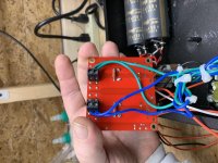
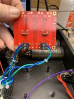
Can someone please confirm that is the correct way for the secondary’s are to be connected to the power PCB?
Just to add, I found which secondary winding were a “pair” by metering them out. So the way they are connected is one blue is connected to a terminal and the matching green for that blue is wired to the other terminal straight across from it. Hope that makes sense.
Just to add, I found which secondary winding were a “pair” by metering them out. So the way they are connected is one blue is connected to a terminal and the matching green for that blue is wired to the other terminal straight across from it. Hope that makes sense.
Attachments
Last edited:
I will not.
On the side of the transformer it shows the blue-green secondary’s and below is how I originally had the wired but kept blowing fuses and right now I have one good 250v .500ma slow blow left until the order I just placed arrived.
I read your PM and responded to it.
Thanks, James
On the side of the transformer it shows the blue-green secondary’s and below is how I originally had the wired but kept blowing fuses and right now I have one good 250v .500ma slow blow left until the order I just placed arrived.
I read your PM and responded to it.
Thanks, James
Attachments
...then what is it?
MC cart has DC resistance of a few tens of ohms.
One of the neat things about LTSPice is that the program allows one to see the specific contribution of each element to overall output noise. I leave it to you to create the files for the Pearl II and the various power supply options. As I mentioned previously, I couldn't detect any diff when the Pearl was powered by the LMxxx regulators or a Jung Super Reg.
For me, the Pearl is in regulator rotation as my phono-pre...
No changes, it’s a mature design. If you have any questions about part substitutions please ask here in the thread.
Order extra ZVP3310 mosfets, about 1/2 the builders blow one during assembly as they are incredibly static sensitive. Having an extra or 3 on had at the beginning is much cheaper than ordering a replacement later.
It seems to me that the ZVP3310 is the one component that should be socketed...to minimize MOSFET Misery Syndrome...
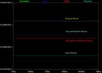
The PSU in the Pearl is more than good - properly built the noise you hear will be a combination of the popcorn of the input Jfets, the Johnson noise of the resistors, or some kind of inductive loading/hum from the cartridge itself.
I know it's off topic, but may i return to this subject for a second.
Does inductive loading/hum usually contribute to the overall noise of a phono stage (especially MM carts with Opamp based phono stages)?
IIRC higher wattage resistors have lower noise than smaller ones, so would CMF60 over CMF55 Vishay's be preferable? And lowest ppm available? (for the posistions you mentioned)
They may have lower "excess noise". if the excess noise is less than 10% of the nominal "random" noise it probably should be ignored (unless you're splitting atoms.) Thin film resistors have low excess noise.
I know it's off topic, but may i return to this subject for a second.
Does inductive loading/hum usually contribute to the overall noise of a phono stage (especially MM carts with Opamp based phono stages)?
An Audio Technica MC cart with DCR of 12R has noise of 63nV over 20 to 20kHz and output of 320uV, so the signal to noise ratio is about 74dB.
An Audio Technica MM like the VM540 has DCR of 800R, noise 510nV over 20 -20kHz and output of 4mV so the signal to noise ratio is about 78dB
The RIAA network has noise of its own, but the slope is -20dB/8vo from 2.12kHz and the ear is most sensitive to noise @6.3kHz.
SY wrote an article, must reading: "His Master's Noise" and while it mostly treats vacuum tube phono-pre, the principles still hold.
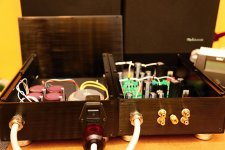
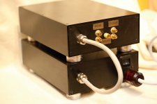
OK, let me see if I can describe this good enough not to need pictures since I cannot get them right now.
Just need to verify wiring of a few items.
Metered out the secondaries and matched the blue and green wires to their respective windings. Blue wires on transformer have the polarity dots.
Have main power in going from plug to one side of on/off switch. Other side of switch is than connected to one side of fuse housing. Other side of fuse housing is connected to both red wires of the transformers primary windings.
Neutral input is being tied to the two black wires of transformers primary windings.
Ground from main input is tied to chassis ground.
Bridge ~ sides are tied together and are connected to chassis ground.
Bridge + and - sides are tied together and are than connected to power PCB +PGND and -PGND.
My question would be since there are no polarity markings on the underside of the PCB where the wire terminals are, does it matter where each blue/green secondary wires are placed. I would believe that one blue/green set would go to AC1 and the second set would go to AC2.
I did this and wired the blues say to the top input and the greens to bottom and matched them on the other wire input.
I did find the below information in another thread about this transformer.
Testing and Utilising torroid on lm3886
“Yes; the two secondary transformer windings can go to either side. Select one of the two blue secondary wires. With an ohmmeter (DMM) determine which of the two green secondary wires is part of the same winding. Once you determine which one (the DMM should read VERY low ohms for the same winding), these go to (for example) the AC1 and AC1 (with the bar overhead) terminals. Check the other two secondary wires (the remaining blue and green) for low ohms with the DMM and connnect them to the AC2 and AC2 (with the bar overhead) terminals. For consistency (but not essential), select the blue wires to go to AC1 and AC2.”


Attachments
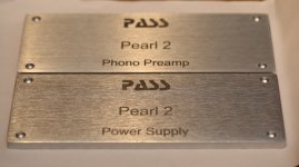
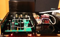
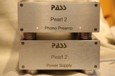
Beauty! Where did you get the feet and how did you do the Pass logo on the front panels?
4pcs 40*20mm Aluminum Isolation Speaker Turntable Stand Base DAC CD Feet Mat Pad 937795188074 | eBay
I got the aluminum fronts sent to Poland for engraving. They did a great job and i am very satisfied.
I got the aluminum fronts sent to Poland for engraving. They did a great job and i am very satisfied.
Last edited:
4pcs 40*20mm Aluminum Isolation Speaker Turntable Stand Base DAC CD Feet Mat Pad 937795188074 | eBay
I got the aluminum fronts sent to Poland for engraving. They did a great job and i am very satisfied.
Thanks, just ordered a set of feet!
- Home
- Amplifiers
- Pass Labs
- Building a Pearl 2