Pass DIY Addict
Joined 2000
Paid Member
Yep. Once done with BA-3 pre start in on BA-3 amplifier. Or F-6! Or Aleph J
Russellc
Yep, Aleph-J project waiting in the wings! All of the parts are bagged together in my project box right now. I'll build it with an outboard PSU so I can switch back and forth from the J to the F4. I missed the PCB buy on Nelson's latest Sony vFet amp - darn!
Edit for Jim: my zpv3310 devices survived the build without needing replacement ;-)
Last edited:
Quick question: how have others arranged ground in their Pearl? Is it "normal" for the 0v pad for the power input to be connected to the unmarked gound pad in the center of the PCB? I only realized this after construction was completed so I am unsure if this is the way the board is designed or an artifact of my wiring scheme. I have a small amount of hum that I presume is the result of proximity to other equipment right now...
somewhere in this thread 6L6 has a nice hand drawn illustration. Yes that small pad near the middle is a ground. Your Pearl should be fairly silent.
Russellc
look at this post, scroll down a couple of pics!
http://www.diyaudio.com/forums/pass-labs/204336-building-pearl-2-a-3.html#post3641444
http://www.diyaudio.com/forums/pass-labs/204336-building-pearl-2-a-3.html#post3641444
The ground in the middle of the board connects to the ground post. I'll dig up a diagram when I not on my phone...
I found it...see post 33-35
http://www.diyaudio.com/forums/pass-labs/204336-building-pearl-2-a.html#post3421878
Russellc
Pass DIY Addict
Joined 2000
Paid Member
Yep, thats the diagram I used. Just wondering if I should have used plactic standoffs to mount the pcb to the chassis. I presume at this point that any noise I have is due to physical proximity to other equipment in my rack. I only hear it with the gain at or near full, at more reasonable listening levels, it is not audible from the listening position.
Your values fit with the calculator, but only when Ro from first stage is zero.
The Zout of the first stage should factor into the final result of the network design, but it's not 499R, it should be much smaller. Zout for a cascade gets into some matrix math...
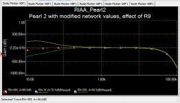
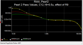
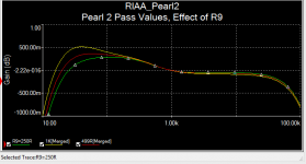
At any rate, I took a look at how the value of R9 would affect compliance to the RIAA curve. I normalized the outputs to 0dB @1kHz. The first chart are the values I am using via Lipshitz with the coupling cap (C12/16) value changed to 1uF, the second are the values from the Pass article and the same change to the coupling cap (1uF), the third uses the 0.2uF values per the schematic.
Attachments
After a long hiatus, I'm finally making progress on my Pearl 2. If all goes well, I'll fire it up tomorrow. Fingers crossed.
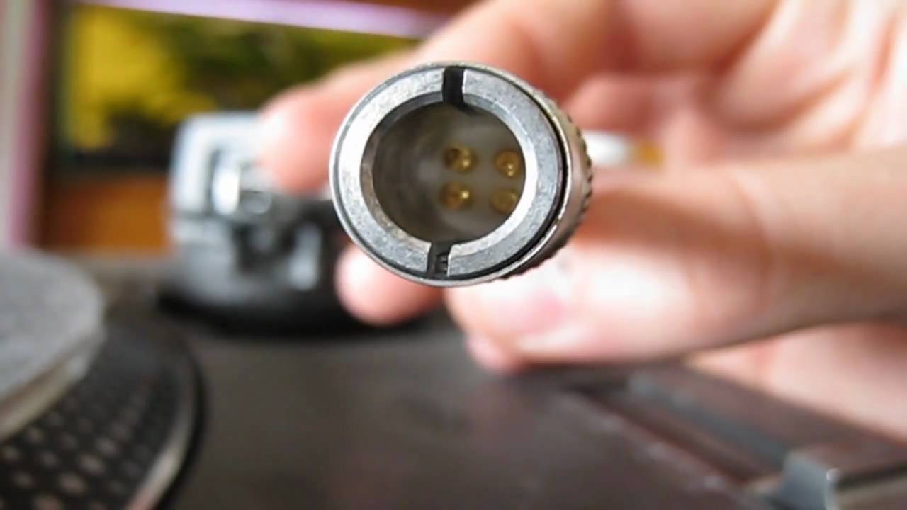
6L6, per your suggestion, I bought an AT 150mxl. And proceeded to drop it onto the counter when I was trying to wrestle it off that little plastic arm it comes mounted on . I attached it to the stock Technics headshell and used the Technics overhang gauge, but I am getting very muddy sound and the left channel cuts in and out. Anybody ever had a problem like this? Is it possible that the azimuth is just really off and I need to keep tweaking (looks pretty good to me)? Or did I break my brand new cartridge?
6L6, per your suggestion, I bought an AT 150mxl. And proceeded to drop it onto the counter when I was trying to wrestle it off that little plastic arm it comes mounted on . I attached it to the stock Technics headshell and used the Technics overhang gauge, but I am getting very muddy sound and the left channel cuts in and out. Anybody ever had a problem like this? Is it possible that the azimuth is just really off and I need to keep tweaking (looks pretty good to me)? Or did I break my brand new cartridge?
Or did I break my brand new cartridge?
If you dropped it, then yes, you probably broke it.
I killed a cartridge cleaning the stylus once.
Pass DIY Addict
Joined 2000
Paid Member
I had a great deal of trouble wrestling my at150 out of its plastic case as well. I stil dont inderstand the mechanism, but I was worried about damaging it in the process. I was hoping they would have provided some written instruction about this...
On another topic, how can I REDUCE the output from the Pearl? Until I finish my BA-3, I've been running it into my Marantz preamp. On almost all albums, the "peak" indicator light up and on many the sound is a bit distorted as a result. I added a 499R in series with the 1k for R14 and it has helped a little, but the peak indicator is still lit. How high can I take R14 without causing trouble? At 1k5, it introduces a little hum at max volume. Is there a better approach to reducing gain?
On another topic, how can I REDUCE the output from the Pearl? Until I finish my BA-3, I've been running it into my Marantz preamp. On almost all albums, the "peak" indicator light up and on many the sound is a bit distorted as a result. I added a 499R in series with the 1k for R14 and it has helped a little, but the peak indicator is still lit. How high can I take R14 without causing trouble? At 1k5, it introduces a little hum at max volume. Is there a better approach to reducing gain?
Last edited:
I
On another topic, how can I REDUCE the output from the Pearl?
I believe that there is a spot for a capacitor "Cx" which is parallel to the 100k feedback resistor -- try putting another 100k resistor in this place. This will cut the gain of the output stage in half. (1)
Note that the AT150 has high output compared to most MM carts.
(1) helpful hint -- when prototyping I use female pin headers in spots like "Cx" so that I can substitute parts without reaching for the soldering iron.
Pass DIY Addict
Joined 2000
Paid Member
Pass DIY Addict
Joined 2000
Paid Member
Excellent suggestion, Jack! Thank you. I already installed a female pin header in this spot as well as C22 and R20 at the input for cartridge loading. This should be easy to play with different values.
Mind sharing what female header part you used and its source?
Thanks,
Russellc
After a long hiatus, I'm finally making progress on my Pearl 2. If all goes well, I'll fire it up tomorrow. Fingers crossed.
6L6, per your suggestion, I bought an AT 150mxl. And proceeded to drop it onto the counter when I was trying to wrestle it off that little plastic arm it comes mounted on . I attached it to the stock Technics headshell and used the Technics overhang gauge, but I am getting very muddy sound and the left channel cuts in and out. Anybody ever had a problem like this? Is it possible that the azimuth is just really off and I need to keep tweaking (looks pretty good to me)? Or did I break my brand new cartridge?
You could have broken it but its worth cleaning and checking the mating pins tension in the tube to headshell joint too.
Pass DIY Addict
Joined 2000
Paid Member
Mind sharing what female header part you used and its source?
Here you go, Russell: 310-87-164-41-001101 Preci-Dip | 1212-1114-ND | DigiKey
Works great for resistor and cap legs.
Here you go, Russell: 310-87-164-41-001101 Preci-Dip | 1212-1114-ND | DigiKey
Works great for resistor and cap legs.
Thanks! Going on my next digikey order! Do you just snap off what you need? Wait a min., looks like data sheet shows how to change it up by altering number....did you get single ones?
Russellc
Last edited:
- Home
- Amplifiers
- Pass Labs
- Building a Pearl 2