I will make a good CRCRCRCRC supply, and then I'm sure it will be quiet
Olle, SY will be really scared about the many RC sections...
He usually says they are more prone to oscillation...?
(Can't comment on that from my personal experience).
What makes me wonder is that you had psu-related hum in your
Aikido... Broskie states that the Aikido circuit has very good PSRR
and recommends a rather simple psu as standard. The noise
suppression qualities (what a word
 ) of the circuit are set by
R15 and R16 when I recall correctly, and it has even been recommended
by people on these forums to use a trimpot in place of R15 to tweak
for best performance.
Was your initial psu that bad (excuse me
) that you had thatmuch hum?
Just being interested...
PS. my Aikido headphone amplifier uses a voltage doubler CRCRC psu and regulated DC heaters and is quiet as space...
Agreed! The 6x5 rectifier tube comes on slow so if the voltage spikes way out of line.....say more than 350V you can turn off the power before any damage occurs. Just wire up the DVM and have a finger on the power switch
Do I need to be measuring the point on the psu where the B+ is connected?
Also can I test the psu without it hooked up to the main board?
When I work with my SS amps i always attach the negative probe on my dvm to the metal chassis and measure the voltages.
How do I measure the voltages on my psu? (where do I attach the negative probe?)
Brit,
Do I need to be measuring the point on the psu where the B+ is connected?
Yes.
Also can I test the psu without it hooked up to the main board?
Yes, but it won't be correct....
When I work with my SS amps i always attach the negative probe on my dvm to the metal chassis and measure the voltages.
Remember that when working with tubes there will be a voltage Bias on the heater circuit, and will show different voltages at different ground points.
How do I measure the voltages on my psu? (where do I attach the negative probe?)
Ground(ing) point
Ron
5687 tubes arrived today.
Hooked everything up.
I am getting 258 V B+ at the moment with a 0.47uF cap in C1 position on Bas's psu which is ok I believe.
I will try adding another cap to see if this raises to experiment.
But I don't have the heater bias connected yet to the virtual center tap.
I don't quite understand what this is for and what effect it has.
if you look at the tube data sheets it will specify a heater to cathode max voltage.
to put it simply, the B+ goes through a voltage divider which is then often connected to the CT of the heater secondary. There is no closed circuit with B+, so no current flows, it just super imposes + whatever voltage you specify. The 6.3v can then vary around that new super imposed potential.
to put it simply, the B+ goes through a voltage divider which is then often connected to the CT of the heater secondary. There is no closed circuit with B+, so no current flows, it just super imposes + whatever voltage you specify. The 6.3v can then vary around that new super imposed potential.
Brit,
Think of the Bias this way:
A-----------B-------------C
0-----------0------------12
A-C = 12Volts
A-----------B--------------C
50---------0--------------12
A-C = 62Volts
B-C = 12Volts
Heaters are powered from B-C
A is Bias from B+ supply
Voltage measured from different points give different results
When the CT of the heater supply is connected to ground the voltage is the first example
When the CT of the heater supply is connected to B+ Bias the voltage is the second example
The B+ Bias basicly raises the 0 (zero) above ground (earth)
If you take 2 AA batteries placed in series, measure the voltage on the extreme ends then measure the voltage from the middle to one end. The voltage is different depending where it is biased from.
I hope that makes sense.
Merry Christmas
Ron
http://syclotron.com/?page_id=8
I've been reading a lot of articles lately and am concerned about my new Aikido lineamp and the amount of gain it will produce.
When I started I was a total newbie and wanted to start with a simple valve preamp to fit into my system, to drive my SS power amp with a Rotel cd player. I believe that the rotel will have about 2V output.
Will it produce too much gain for the power amp? The power amp is a Carver TFM-55, but it has a line level control which I imagine will be very useful to match it with the gain of the Aikido (6N1P/5687).
These days, a preamp is almost redundant. Signal sources in my living room include CD, DVD, satellite/cable, a dedicated phono stage, and MP3, not an untypical mix. All have roughly 2V output at a low source impedance. My power amps are of normal sensitivity (as probably are yours), so we really only need unity gain. A10K input impedance is fine- there will be no weedy sources allowed in MY system!
I've been reading a lot of articles lately and am concerned about my new Aikido lineamp and the amount of gain it will produce.
When I started I was a total newbie and wanted to start with a simple valve preamp to fit into my system, to drive my SS power amp with a Rotel cd player. I believe that the rotel will have about 2V output.
Will it produce too much gain for the power amp? The power amp is a Carver TFM-55, but it has a line level control which I imagine will be very useful to match it with the gain of the Aikido (6N1P/5687).
No hum!
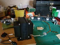
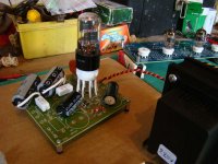
I have spent some time with my aikido lately
The old supply with the choke wasn't clean. I think it was self-oscillating!
So I removed it, and then I built a normal CRCRC-supply!
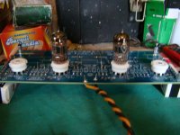
Note the green (round) caps on the last picture. I think it's important to have some film-caps near the signal-circuit!
What are these caps called? I don't know the word in english...
The result: The amplifier is dead silent!
Left to do: Change the power supply resistors to new ones with a little higher values! My goal is 220V B+, because John Broskie wrote so in the schematic. It's about 270V as it is now...
I have spent some time with my aikido lately
The old supply with the choke wasn't clean. I think it was self-oscillating!
So I removed it, and then I built a normal CRCRC-supply!
An externally hosted image should be here but it was not working when we last tested it.
An externally hosted image should be here but it was not working when we last tested it.
An externally hosted image should be here but it was not working when we last tested it.
Note the green (round) caps on the last picture. I think it's important to have some film-caps near the signal-circuit!
What are these caps called? I don't know the word in english...
The result: The amplifier is dead silent!
Left to do: Change the power supply resistors to new ones with a little higher values! My goal is 220V B+, because John Broskie wrote so in the schematic. It's about 270V as it is now...
About the sound: I think it is very good!
I have a Squeezebox music-player with integrated volume control. I have used this volume control to limit the signal to my my RH84 (an EL84 SE tube amplifier) before I built this preamp.
So i adjusted the output signal to 100% (I think it is about line level output) and connected the player to the Aikido, and the aikido to the tube amplifier.
I'm not sure if I can hear the difference between aikido, or no aikido
Maybe I have to listen more, and then I may discover some differences, but I haven't noticed anything yet
It must be a sign of low distortion John Broskie is probably right
I have a Squeezebox music-player with integrated volume control. I have used this volume control to limit the signal to my my RH84 (an EL84 SE tube amplifier) before I built this preamp.
So i adjusted the output signal to 100% (I think it is about line level output) and connected the player to the Aikido, and the aikido to the tube amplifier.
I'm not sure if I can hear the difference between aikido, or no aikido
Maybe I have to listen more, and then I may discover some differences, but I haven't noticed anything yet
It must be a sign of low distortion
John Broskie is probably right Re: No hum!

Well done Olle, I can only hope mine is as nice as yours.
Have you looked at the "curve" of your tubes to find out what/where 220V is compared to 270V?
1/2 of 220 is 110 (Aikido splits the voltage)
1/2 of 270 is 135 ........Only 25V difference. Let us know if you hear a difference when you change out the resistors, please.
Ron
ollebolle said:
The result: The amplifier is dead silent!
Well done Olle, I can only hope mine is as nice as yours.
Have you looked at the "curve" of your tubes to find out what/where 220V is compared to 270V?
1/2 of 220 is 110 (Aikido splits the voltage)
1/2 of 270 is 135 ........Only 25V difference. Let us know if you hear a difference when you change out the resistors, please.
Ron
yes good work Olle.
Great you have it hooked up playing music now. I've just got back from vacation so i can get started on the chassis and put everything in place.
I will first test it with some cheap self-powered speakers I use for the computer.
Then if all is well and reading correctly I will hook it up to my solid state power amp and Klispch speakers.
I'm already planning my next tube amp with KT88's or EL34's.
Drawing out some designs and reading loads of ideas.
Keep us updated Ron.
Re: Re: No hum!
Thank you guys! I'm glad it finally works!
I have thought about the B+ voltage..
This is the schematic from his article back in 2005:
http://www.tubecad.com/2005/January/blog0030.htm
This is the schematic I have used, so my components have these values
This is how I understand the schematic:
The values of the components are calculated for 6N1P:s and 5687:s at a B+ of 220V.
And if I change the B+, I will have to change some values, right?
Then I looked up John Broskies aikido PDF, and found a table with data for different tubes!
The table contains values of some components at 200V +B, 250V and 300V!
I can find the input tube, 6N1P, but not 5687...
About the curves, or load lines:
I can't calculate load lines, and i don't know all the theory behind it
Do you think a higher B+ would give a better load line, and better performance?
Thank you guys! I'm glad it finally works!
Renron said:
Have you looked at the "curve" of your tubes to find out what/where 220V is compared to 270V?
1/2 of 220 is 110 (Aikido splits the voltage)
1/2 of 270 is 135 ........Only 25V difference. Let us know if you hear a difference when you change out the resistors, please.
Ron
I have thought about the B+ voltage..
This is the schematic from his article back in 2005:
http://www.tubecad.com/2005/January/blog0030.htm
This is the schematic I have used, so my components have these values
This is how I understand the schematic:
The values of the components are calculated for 6N1P:s and 5687:s at a B+ of 220V.
And if I change the B+, I will have to change some values, right?
Then I looked up John Broskies aikido PDF, and found a table with data for different tubes!
The table contains values of some components at 200V +B, 250V and 300V!
I can find the input tube, 6N1P, but not 5687...
About the curves, or load lines:
I can't calculate load lines, and i don't know all the theory behind it
Do you think a higher B+ would give a better load line, and better performance?
The table shows all the input tubes. 5687 is not shown as it is the output tube.
JB's new board is slightly different.
I am using 470 ohm cathode resistors as the 6N1P have an average mu value. He says to use higher value cathode resistors for high-mu triodes.
He also mentions running the output tubes hotter, not sure why exactly, I understood it was so you could change the output tubes with the input tubes as they wear out quicker but with this design you cannot.
I have the cathode resistor values equal for input and output tubes.
B+ is currently 260 V.
I'm going to decrease the bias as JB recommends 1/4. Mine is currently 1/3 of the B+.
- Home
- Amplifiers
- Tubes / Valves
- Building a Aikido preamplifier