you guys who may not have done much SMD should really grab yourself some separate solder flux.
I have been using the Kester 951 and like it, but some might like flux that is more gooey. I spilled a bottle the other day though, not brilliant near a furnace. Better to invest in a applicator bottle that has a needle, vs the open bottle and the big eyedropper thing. Or maybe a medical syringe with sharp end chopped off? The type of iron with a nice plated tip is working great for me SMD, and with a larger tip than you would imagine - holds heat better. I seem to fall into the higher heats category but have been at it decades and know how to do it. I'm finding with just leaping into SMD, the flux ala carte is a huge help. Maybe I need a hollow tipped iron and a flux-pump ? [joking] The flux cleans, but I think it must help migrate heat a bit, no? Often I end up holding the tiny caps with my finger, if I get burnt then maybe it was too much heat. Soon I will dig out my PCB vice. I have the damp sponge but usually wear jeans and clean the tip on my leg too, stays hotter.
If using Crystek CCHD-950/957, no bypass is necessary.
I am thinking of fitting something that can accommodate Ian's oscillator carrier boards. Haven't figured out how. Maybe make a frame with a piece of protoboard...
I'd like to see that. Not easy to do !
The socket isn't great but it's intended as a temporary way to let me evaluate different xo's.
I've changed C1 - I'll try 2nF ....if no-one objects ;-)
An externally hosted image should be here but it was not working when we last tested it.
The Buffalo DAC also has a single 1.2v regulator. Elsewhere it was explained that the 1.2V is a "holding" voltage. I wouldn't worry about separating the 1.2V supply.
I plan to use .1 uF bypass everywhere and parallel them with 10 uF on the digital/analog 1.2V and the digital 3.3V. On the Analog 3.3V I would just use 0.1uF bypass (and maybe a smaller one in parallel).
TPS7A47 seems a good candidate for the 3.3V digital (which also feeds the ADP 1.2v)
and Salas LV/Placid/other shunt seems a good choice for the analog 3.3 which benefits from shunt regulation
the buffalo 1 and II also use an LDO for clock.... its a compact design, but its not a benchmark IMO. it needs work to gain best performance, but they allowed for that. the fact that this one made it impossible to separate the 2..erm 3...6 is the more concerning part.
You can separate the 1.2v from the 3.3v if you wish. And even power the clock with another supply. The only supply that cannot be separated is the left AVCC from the right AVCC.
No one is expecting this board to beat the Buffalo DAC or the Acko DAC. And no one is taking any merit away from those two superbly designed DACs. There is space for every price point, and this an excellent platform to experiment and learn.
No one is expecting this board to beat the Buffalo DAC or the Acko DAC. And no one is taking any merit away from those two superbly designed DACs. There is space for every price point, and this an excellent platform to experiment and learn.
You can separate the 1.2v from the 3.3v if you wish. And even power the clock with another supply. The only supply that cannot be separated is the left AVCC from the right AVCC.
No one is expecting this board to beat the Buffalo DAC or the Acko DAC. And no one is taking any merit away from those two superbly designed DACs. There is space for every price point, and this an excellent platform to experiment and learn.
ah, not my words, I dont have the board, it doesnt look like it would be easy to do and KK said they appeared to be joined under the chip. thats why I sked specifically about that.
Last edited:
Misunderstanding guys - what I think - you can't separate the digital and analogue 1.2V from each other.... the routing division is under the IC.... so you'd need to desolder the IC, and then have a look. I have a friend who can do that but it's way beyond me. Everything else seems possible.
I have been using the Kester 951 and like it, but some might like flux that is more gooey. I spilled a bottle the other day though, not brilliant near a furnace. Better to invest in a applicator bottle that has a needle, vs the open bottle and the big eyedropper thing. Or maybe a medical syringe with sharp end chopped off? The type of iron with a nice plated tip is working great for me SMD, and with a larger tip than you would imagine - holds heat better. I seem to fall into the higher heats category but have been at it decades and know how to do it. I'm finding with just leaping into SMD, the flux ala carte is a huge help. Maybe I need a hollow tipped iron and a flux-pump ? [joking] The flux cleans, but I think it must help migrate heat a bit, no? Often I end up holding the tiny caps with my finger, if I get burnt then maybe it was too much heat. Soon I will dig out my PCB vice. I have the damp sponge but usually wear jeans and clean the tip on my leg too, stays hotter.
yes well actually I find both liquid and tacky flux have their purpose. liquid, with applicator bottle is good for running up large IC sides and the stickier stuff applied with a stick or small pallet can help to hold it in place till you tack the corners down; as well as its normal function. yes it helps migrate the heat but mainly because it helps the metal to flow.
stay away from the sponge IMO, grab yourself some brass wool wet sponges oxidise the tip and give thermal shock, the tips wont last as long and dont tin as nicely.
Misunderstanding guys - what I think - you can't separate the digital and analogue 1.2V from each other.... the routing division is under the IC.... so you'd need to desolder the IC, and then have a look. I have a friend who can do that but it's way beyond me. Everything else seems possible.
no thats how I understood you and its what it looked like to me from looking at the photos, thus why I asked you to confirm. forget removing the chip, even professional pick and place joints wont warranty that the chip will still work if you ask for removal.
If using Crystek CCHD-950/957, no bypass is necessary.
I am thinking of fitting something that can accommodate Ian's oscillator carrier boards. Haven't figured out how. Maybe make a frame with a piece of protoboard...
Here is what I've done (not much, but it is a start
") ): Building the $99 ES9018 DAC Board H i F i D U I N O
): Building the $99 ES9018 DAC Board H i F i D U I N O
Last edited:
Here is what I've done (not much, but it is a start
Great stuff !

And that's a very cute xo board... damn I'm jealous...

Esp. compared to my horribly-wrong impedance op amp socket...

Thanks for posting current demands and that info about supplies. Total current = ~205 mA ? The Sigma11 should do nicely for AVCC = uZ output impedance.
Last edited:
The cute XO carrer board, I just bought them from Ian as part of the FIFO kit. I think socket is OK. Ian uses them in the FIFO clock board. In fact he also has a clock adapater board for the Buffalo III where you install the clock on the clock carrier and then you plug it into a socket in the adapter board and the adapter board uses pins to connect to the BIII board. I was thinking that way first, but removed the pin socket...
Total current is that plus what the regulators consume. So for AVCC that would be 64 mA plus the additional shunt current to keep the regulator working at max current consumption, say 10-50 mA? depends on the design. AVCC also depends on the voltage you use and oscillator frequency. The 64 mA value is likely for 100 MHz and 3.6V. There is a AVCC power consumption chart in the ESS tech docs.
The sigma 11 looks nice. I'll have to take a closer look. I've always liked AMBs stuff.


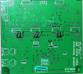
2013 January version. Es9018 board
Here are pictures of the front and back of he board I got today.
Have we gotten to where say his/their new ~$65USD Isolated I2s receiver board can mate directly with header pins?? No flying wires to the clocks and I2s?? As a daughter or piggy-back arrangement?
Is THIS the rumored 4-layer PCB?
It looks like there is already a new version of the board. GLT's board has a date of 2012.12. The board I got today is dated 2013.01. There are minor wire trace changes and the addition of extra bypass capacitors. I will see if I can get a picture up later.
A work in progress eh ? I can see there are now two positions for power supply caps for the op amps, which is more convenient, and the I2S can now be gsgsgsgs more easily so that'll be better for cabling/signal integrity.
GLT - the Sigma11 is excellent. All I did for this application was change the zener reference to two red leds (gives 3.8V output, no gain), and I used MUR120 for rectification, just cos they will allow a lower profile build.
Last edited:

The G-mod
An externally hosted image should be here but it was not working when we last tested it.
An externally hosted image should be here but it was not working when we last tested it.
An externally hosted image should be here but it was not working when we last tested it.
An externally hosted image should be here but it was not working when we last tested it.
An externally hosted image should be here but it was not working when we last tested it.
- Status
- Not open for further replies.
- Home
- Source & Line
- Digital Line Level
- Build thread for Diyinhk ES9018 DAC on Ebay