CPU cooler
I would like to explore the idea of using a cpu cooler. I see that various have shown promising results, but I cannot find anyone talking about how one physically attaches the Mosfet to the cooling plate. Do you just drill and tap a hole in the cooling plate of the cooler? Also, how do you attach the cooler with fan to the chassis?
Finally, do you use flying leads with the Mosfet or do you connect the pcb to the cooler in some way?
Thanks for any help anybody can give me.
Jazzzman
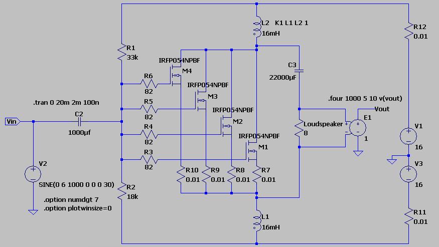
Hello I am here with new measurements using ADALM2000.
I don't know why the slew rate is low in both the amplifiers, Pathos declare value of 38V/usec here.
Transconductance?
The transconductance of the IRFP250 at these voltages is not at its best.
Maybe the reason why i like the irflb3813 and its bigger brother. The input capacitance can be dealt with a beefier preamp
I would like to explore the idea of using a cpu cooler. I see that various have shown promising results, but I cannot find anyone talking about how one physically attaches the Mosfet to the cooling plate. Do you just drill and tap a hole in the cooling plate of the cooler? Also, how do you attach the cooler with fan to the chassis?
Finally, do you use flying leads with the Mosfet or do you connect the pcb to the cooler in some way?
Thanks for any help anybody can give me.
Jazzzman
Hi Jazzzman,
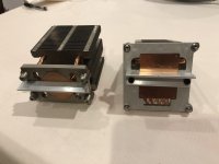
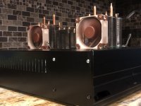
I have used cpu coolers and Noctua fans for several builds with great success. They are a bit awkward to incorporate into an attractive chassis, but they allow you to build extreme projects not possible with conventional aluminum finned heatsinks. Like 4A @ 37vdc for example, Monster MoFo!!

You need a separate 12vdc source to power a PWM fan control board, get them on eBay. Automatic speed control by temperature sensor and dip switch setting. Builders are resistant to use fans because they are “noisy”, but Noctua fans even on a medium speed are just about silent.
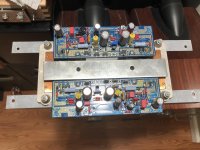
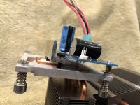
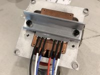
The heat sinks of choice are dell OEM units with large copper bases. You drill and tap into the aluminum that surrounds the copper and use an angle aluminum clamp bar. I’ve used both the flying lead methods and also mounting the PC board directly on the CPU unit. The MoFo is absolutely perfect for this setup, single output device and a small pcb.
Attachments
-
 D96E1CBE-7262-4974-AB57-B0C3C9451E1C.jpg735.2 KB · Views: 513
 -
 CD25A45C-DE66-4357-A6A3-CD0563B8034F.jpg1 MB · Views: 519
 -
 66FFC622-56DC-49A7-9CBF-479D8F05E7CF.jpg849.3 KB · Views: 495
 -
 AB019AC6-DE07-4E50-B5FA-D4728BF0BE6C.jpg1 MB · Views: 484
 -
 F652D074-D74C-439F-ACED-8823586DE55D.jpeg563.6 KB · Views: 481
 -
 475E7339-891E-45A0-92F6-1D1DEB46C940.jpg794.5 KB · Views: 288
CPU Cooler
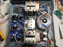
Vunce, after studying your pictures a little more, I do have a couple of questions, if you don’t mind. In photo 4, it appears in the upper left you have the fan ps and controller. What is the pcb in the lower right corner? How tall is the Dell cooler? Also, which inductor are you using. Finally, does the transformer have dual voltages? Which transformer did you use? Thank you again.
Jazzzman.
Hi,
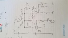
After frying some verticals due to thermal runaway, found the idea to track bias inversely climbing bias.
Using TL431 biased after a sense resistor.
After ZEN warned me about laterals, decided to use verticals.
Comments please.
Regards
Mehmet
Attachments
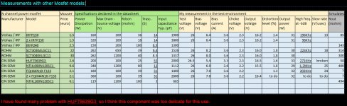
Here more data about mosfet choice, the FQH44N10 is better than IRFP150NPbN aso if I cannot simulate the Rout because there is no spice model available.
The thd level is refered to the complete amplifier with 6072A driver.
Also the NTHL080N120SC1 is an interesting device with a band of 1.2MHz but there is a very high Rout and the slew rate is only 25V/usec.
Obviously I have to measure also the slew rate of the driver to know the limit of this. http://www.audiodesignguide.com/Inpol/NTHL080N120SC1-D.PDF
Attachments
MoFo project
Im just puting together this project inspired by all diy members and have a few questions.Becouse my speakers are 4 Ohms I have thinking to use 19V power supply pro monobloc and bias than the amp to around 2,5A.I already have 4 pieces hammond 159ZE(28mH 3A) inductors from my hiraga ClClC psu and I would ask if I can use two per monoblocc conected in series in this case I become 56mH and still 3A ,or is this bad idea and better to use only one choke somethink like hammond 193V.I will put this together like point to point wiring with big heatsing about 0.50C/w and using this with my 6n6p srpp pre.I will put 10000uf 25V output capacitor I hope this is OK.Another question,I see some diyers using zener diode 20V on pcbs,but I dont see this on schematic,where I must conect this zener,I think is only protection diode or????So this are my question for now.
Im just puting together this project inspired by all diy members and have a few questions.Becouse my speakers are 4 Ohms I have thinking to use 19V power supply pro monobloc and bias than the amp to around 2,5A.I already have 4 pieces hammond 159ZE(28mH 3A) inductors from my hiraga ClClC psu and I would ask if I can use two per monoblocc conected in series in this case I become 56mH and still 3A ,or is this bad idea and better to use only one choke somethink like hammond 193V.I will put this together like point to point wiring with big heatsing about 0.50C/w and using this with my 6n6p srpp pre.I will put 10000uf 25V output capacitor I hope this is OK.Another question,I see some diyers using zener diode 20V on pcbs,but I dont see this on schematic,where I must conect this zener,I think is only protection diode or????So this are my question for now.
Thanks Michael for your reply.But plese be so nice and tell me if it will be enough to have 19V psu with 2,5A of bias for 4 ohm speakers,or shuld I go liwer with psu like 15-17 volts and maybe bias the amp to about 3A??I have buy Irfp250 from mouser that I will use in this project and all other parts are the same value like in schematic.And what about chokes that I have,can I use only one per monoblock so 28mH 3A or can I put together in series two,to have about 56mH inductor.I know in this case I will have about 0.86 ohm of DCR insteed of 0.43 ohm DCR if I use only one choke,but to me it is important that the sound will not become worse if I use two chokes conected in series.Plese for answer about this.
what about putting one inductor on the drain and another on the source of the mosfet?
output taken at source and drain of mosfet
if the 2 coils are bifilar wound on the same core, the opposite DC current cancel the flux
It is done on LAPS SLAPS for SLAM!
output taken at source and drain of mosfet
if the 2 coils are bifilar wound on the same core, the opposite DC current cancel the flux
It is done on LAPS SLAPS for SLAM!
Last edited:
- Home
- Amplifiers
- Pass Labs
- Build This MoFo!