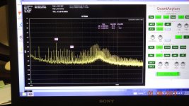
Here are 3 pictures of an HP334A used only for its variable frequency null feature..... (not used for a distortion analyzer). An oscillator (ShibaSoku AG16B) goes into the 334A and the output monitor on the 334A goes to a QA400 ADC/FFT. The 334A range is on its -50dB scale or .3% (fs=1v = 0db). The auto-null is a big plus and keeps everything locked and steady very well. With manual only, there is too much drift off null.
1. measured source shows the QA400 may be the limitation at just a tad below -100 for 2H. In reality it is much lower. Source generator ground floating.
2. Same but with souce generator grounded to chassis.... lots of noise picked up/loops created.
3. 334A still tuned to 1KHz but the source gen freq increased to 1.04Khz. You can see the notch filter atten affect on the 1.04KHz signal.
Seems it has potential to be a useful instrument for nulling DUT signal for ADC/FFT input and other R&D apps.
Thx-RNMarsh
.JPG")


1. measured source shows the QA400 may be the limitation at just a tad below -100 for 2H. In reality it is much lower. Source generator ground floating.
2. Same but with souce generator grounded to chassis.... lots of noise picked up/loops created.
3. 334A still tuned to 1KHz but the source gen freq increased to 1.04Khz. You can see the notch filter atten affect on the 1.04KHz signal.
Seems it has potential to be a useful instrument for nulling DUT signal for ADC/FFT input and other R&D apps.
Thx-RNMarsh
Attachments
Last edited:
It's not the QA400, it's the HP334. That strong 2nd H is why I gave up on the 334. My opinion -- it's better to use an active Twin-T. When using a spectrum analyzer, it's not necessary to achieve a deep null, -60dB null is plenty. Note that replacing the input buffer amp of the 334 with a good low-noise FET-input opamp like the LT1468 or OPA1641, etc., will reduce distortion, b ut not enough.
Last edited:
Here you go: http://cp.literature.agilent.com/litweb/pdf/00331-90006.pdf The HP 334 includes the RF detector, not an issue for you. Otherwise 331-334 are the same.
@1audio -- Except that the 331 and 332 do not have auto-tune.
@RM -- I never successfully figured out what caused the 2nd H (or the 3rd, for that matter, but eliminating the 2nd would take care of the 3rd). I replaced the null system amps with opamps, but no joy. Certainly, the relatively hi-Z of the tuning circuits is a factor, but I think I also had common-mode issues with the amps.
As I see it, the alternative is to re-build the 334 as a Twin-T with auto nulling, which is relatively easy -- just a lot of work because almost everything gets replaced; I just haven't yet circled back around to mess with that -- maybe this winter. But those are big mods both mechanically and electrically; probably easier to just build a whole new box....
@1audio -- won't necessarily play havoc -- the 334 has fixed gain on the throughput to the monitor output once adjested for "set level", so the scaling of harmonic products in the FFT display is tied to a fixed reference level -- in the 334, to 1VRMS. This is not the case with the HP8903 and some other analyzers, however, where the instrument manages the throughput gain without telling you what it actually is.
I just did a thru-put thd test on the 334 using the ShibaSoku analyzer. The test was from input to output withOut null in operation. The distortion is all there... 2H and 3H. However, the 3H is higher than 2H in level. Not what the QA400 indicated. The high 2-3H levels seen is due to the single-ended amp topology and the use of electrolytic coupling caps. Maybe a control pot, as well, for the high 3H.
I can drop in some low thd bipolar electrolytic for coupling caps to get a feel for how much they contribute vs the amps. However, I dont need it for an analyzer and might find a way to come in after all the front end stuff and go direct or buffered into the null circuit... bypassing the amps contribution to the distortion generation.
Thx-RNMarsh
@RM -- those are good ideas -- I wasn't aware of the major impact of capacitor types on low-level distortion when I was fooling around with the 334, so ordinary polarized electrolytics were what I had and used. Now I know better, so maybe this is really important. Note that my high distortion levels were not due to single-ended amps -- I built an entirely new null amp board with opamps and still had high residuals -- much better than stock, but not near good enough.
We have a preamp before the null/rejection bridge and a post bridge amp. Thats it. If they are clean, the residual output will be good. Electrolytics are known to have high 2H so that is first point of interest to eliminate.
The auto-null works really well and would be a help to any type rejection (Twin-T etc). I can leave it at a set null frequency and no other freq close to it pulls the notch over to it nor any drift. That and continuously variable freq are the best points for a freq notch filter feature addition. Hope we can make it work... worth a few more looks.
Thx-RNMarsh
Last edited:
@RM -- don't forget the overall feedback that makes this a high-Q active filter. I'm going to simulate a Wien-Robinson topology which if usable in the general 334 filter scheme, would have no common-mode issues (all inverting amps) and a realtively easy auto tuning setup....
@1audio -- won't necessarily play havoc -- the 334 has fixed gain on the throughput to the monitor output once adjested for "set level", so the scaling of harmonic products in the FFT display is tied to a fixed reference level -- in the 334, to 1VRMS. This is not the case with the HP8903 and some other analyzers, however, where the instrument manages the throughput gain without telling you what it actually is.
If I use either the QA400 or an automated unit like the Shibasoku the levels reported relate to the fundamental. With autonull that depth will be a moving target making the indications hard to follow. If the "notch" gets a parallel path to set the maximum depth then its more useful.
If I use either the QA400 or an automated unit like the Shibasoku the levels reported relate to the fundamental. With autonull that depth will be a moving target making the indications hard to follow. If the "notch" gets a parallel path to set the maximum depth then its more useful.
We should try it, then.
-RM
We should try it, then.
-RM
But, first we need to reduce the 2H-3H distortion.
It looks like you could replace the existing amp stages with these http://www.ti.com/lit/ds/symlink/lme49860.pdf and a small tweak to the power supply (+/-25V to +/-22V) . It would take some planning but replacement PCB's might be pretty simple to graft in. Much of the circuitry on the existing boards would be replaced. The impedances are still very high in the notch filter.
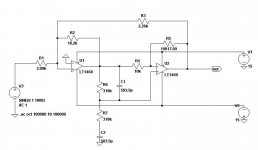
I quickly made an LTspice sim of the Wien-Robinson notch filter; I'd never heard of this filter until today, when a I got a book called "Circuit Design: Know it all," from Newnes Press. Turns out the circuit is very similar to one I designed myself when i was trying to get the HP334 to work better. Sadly, this circuit, like nearly any for a Wien notch filter, still has a diff amp for the post-filter amp, so common-mode issues will be there....
Here are the design steps for this filter (I chose the circuit values to be in the mid-range of impedances, but the tuning Rs (R6, 7) and Cs (C1, 2) are roughly those found in the 334 at 1kHz):
1. Pick f, R, and C for tuning using f=1/2Pi*RC.
2. Pick a filter Q -- I ended up with a Q of 3, which gives a 2nd H. attenuation of about 0.25dB.
3. Pick a throughput gain, A -- I chose unity. The 334 filter system attenuates by a factor of 3, which is not good from a s/n point of view, so unity gain should improve that by about 10dB, but will mess up the output scale on the front. To keep things as they are in the 334, a gain of -10dB (0.3162) could be used, but I haven't looked at what that does to parts values....
4. Calculate alpha = 3Q–1
5. Calculate Beta = A*3Q
6. Define R2
7. Calculate R1 = R2/Beta
8. Calculate R3 = R2/alpha
The 334's auto-tune adjusts R6 and R7 to tune for phase, so that should still work OK in a 334 mod. Varying either R4 or R5 adjusts the amplitude balance, and the stock system also should be usable in a 334 mod, though auto-tune signal polarity will need to be checked.
Attachments
...
I need a 334A schematic ...
This is the "final" one:
http://www.home.agilent.com/upload/cmc_upload/All/333A_334A_Final.pdf
In looking at the manual's Block Diagram (Fig 4-1) and schematic.....the straight-thru distortion from input to output while in the voltmeter function/mode is pretty high. I would look at the crude meter circuit hanging off the output first, then the input buffer amp (Impedance Converter) to reduce the 2H.
Thx-RNMarsh
Thx-RNMarsh
Last edited:
- Status
- This old topic is closed. If you want to reopen this topic, contact a moderator using the "Report Post" button.
- Home
- Design & Build
- Equipment & Tools
- Build -- Active Twin-T notch filter for distortion analysis