Any amplifier will have a sufficiently high input impedance to make the output of the DAC chip act as a voltage source. Another way of looking at this is that you need an input impedance of around zero ohms for it to *not* act as a voltage source (ie a current source) and nobody makes amps like that.
In my case to connect the DAC as voltage source to SE load a "cold" or "-" output of the DAC shall be left floating and not connected to GND, otherwise the DAC chip will be damaged, as a result of draining the current to GND?
Last edited:
I'd like to report this question - it got lost in a deep discussion about ribbon connectors.
===============================================
I'm interested in any opinions from BIII users as to the exact meanings and effects of some of the switch settings.
I'm only using SPDIF input, mostly red book. So what effect do these settings have, or are they even relevant?
- Quantizer setting
- Differential mode
- FIR Roll off (and what does this filter do exactly?)
Ok I will take my best shot...
Some of this is not in the datasheet but I don't think I am spilling any secrets.
Each DAC has a finite number of switched output elements for its analog outputs - out and outB. Using true diff, forces the outB to be EXACTLY the inverse of out. As a consequence, there are many ways to configure the DAC operating in different channel modes. I will talk about the 8 channel and 2 channel configurations then you can deduce the rest I think.
------------------------------------------------------
8 channel:
8.a TRUE DIFF & 6 bit quntizers. Routes 6 bits to dac and the exact same 6 bits inverted to dacB. This is what "true deferential" means.
8.b PSEUDO DIFF & 7 bit quantizer. Routes 1/2 of the 7 bits to DAC (6 bits) and the other half of the 7 bits INVERTED to dacB. Note that the bits are no longer identical and you now need the difference of the 2 for the correct signal. This mode witll give lower quantization noise in theory, and may even "sound better" but the ESS DNR measurement was about 0.5dB to 1dB worse than the TRUE DIFF & 6 bit quntizers.
------------------------------------------------------------------------
2 channel: (always parallel all of the outputs!!!)
2.a TRUE DIFF & 6 bit quantizer. Must now duplicate digital input signal into all channels (4 Left dac1/3/5/7, 4 Right dac2/4/6/8) (some of this can be done internally)
2.b PSEUDO DIFF & 7 bits. Must now duplicate digital input signal into all channels (4 Left dac1/3/5/7, 4 Right dac2/4/6/8)
2.c TRUE DIFF & 7 bits. Must now duplicate digital input signal into 1/2 channels (2 Left dac1/5, 2 Right dac2/6)
2.d PSEUDO DIFF & 8 bits Must now duplicate digital input signal into 1/2 channels (2 Left dac1/5, 2 Right dac2/6)
2.e TRUE DIFF & 8 bits Must now input signal into 1/4 channels (1 Left dac1, 1 Right dac2)
2.f PSEUDO DIFF & 9 bits Must now input signal into 1/4 channels (1 Left dac1, 1 Right dac2)
Note that the input signal connections can be made on the board by physically tying the digital signals together, and/or you can have the chip map some the the inputs internally. (Which what the remap switch does and what Buf-II did all the time) The remap maps 3->1 and 7->5, 4->2, 8->6 by the channel mapping regsiter, and now 2.a and 2.b don't require external mapping of the input signal. In 2.c and 2.d, 4 digital data paths are shut down, and the other 4 drive the output sections. In 2.e and 2.f 6 channels are shut down, and 2 channel drive *all* analog sections.
The FIR roll off selects between two sets of FIR coefficients. One with a slow roll off and one with a sharp roll off. Some will prefer one or the other. Try both see which you like best. You can look at the datasheet for more info here.
Cheers!
Russ
Last edited:
In my case to connect the DAC as voltage source to SE load a "cold" or "-" output of the DAC shall be left floating and not connected to GND, otherwise the DAC chip will be damaged, as a result of draining the current to GND?
Likewise I don't understand if BIII in default configured to 8ch input and output or only 4ch, according to "More than 4 inputs" chapter on page 14 of the Guide?
How shall I treat with inputs of BIII when paralleling it's outputs? In the Guide there is only option for stereo mode is mentioned and without explaning its meaning, ways of utilization a statement - "one can also join inputs... This allows a flexible number of channels to be used".
Can I input to BIII stereo source: phisicaly with 2ch I2S data connection and virtualy with all 8ch I2S data connection when it configured to 8ch input and output and take 2ch output?
Thanks for help.
Regards.
Last edited:
Russ, would you care to elaborate on the reasons behind your choice of the DA1101C transformer used in the 4 channel SPDIF module, and why not something else like say, the Newava S22083? Will the circuit suffer if other pulse transformers are used? Thanks in advance for your input ")
We actually twated a handfull of different transformers when prototyping (nothing exotic). We have used the Newava in the past and they worked well. We got similar performance from the Murata, and they are significantly cheaper, so it helps keep costs down.
You can use other transformers. The Newava has the same footprint. If you try something else, the rest of the circuit is fully configurable. (You will need to do your own research for that however).
You can use other transformers. The Newava has the same footprint. If you try something else, the rest of the circuit is fully configurable. (You will need to do your own research for that however
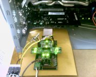
).I have successfuly running BIII playing mp3, flac, dts-hd msr, mlp files.
However there are some problems.
Don't know why but pot isn't working, when I turn the pot cw sound disappear imediately and BIII needs to be turned off, windows volume control is working.
In my BIII only two channels are working. I switched DIP input remapping setting to Off, diff. mode - true, didn't install any jumpers.
Also have a turn on-off thump, but it can be from sound card as was before.
Any thoughts how to make it work as intended?
Attachments
Last edited:
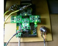
I have successfuly running BIII playing mp3, flac, dts-hd msr, mlp files.
However there are some problems.
Don't know why but pot isn't working, when I turn the pot cw sound disappear imediately and BIII needs to be turned off, windows volume control is working.
In my BIII only two channels are working. I switched DIP input remapping setting to Off, diff. mode - true, didn't install any jumpers.
Also have a turn on-off thump, but it can be from sound card as was before.
Any thoughts how to make it work as intended?
AndriyOL,
Good work so far!
I am sure we can sort you out, but lets move the conversation to the support forum so as not to spam the thread with help for your specific build.
Thanks!
AndriyOL,
Good work so far!
I am sure we can sort you out, but lets move the conversation to the support forum so as not to spam the thread with help for your specific build.
Thanks!
Ok, no problem.
Extracted from leon van Bommel B3 manual in your web site:
"The standard board requires an input voltage of 5.25V and it draws approximately 440mA when one is using the recommended set of Trident shunt regulators"
Are you sure the B3 draws 440mA with combo Tridents connected?
"The standard board requires an input voltage of 5.25V and it draws approximately 440mA when one is using the recommended set of Trident shunt regulators"
Are you sure the B3 draws 440mA with combo Tridents connected?
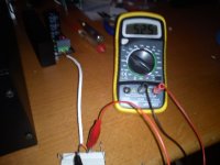
merlin...
Why not measure yours? I have been following your problems on the Salas Bib thread, and it appears to me that you have some kind of problem, as over 700 mA in the reg should be plenty. I have found the Bib regs to work great with only 100 mA shunt current, and I doubt the B-II is drawing more than 500 mA.
If I were you I would measure the current draw on your B-III with your meter.
That's the measurement of Russ and at least 2 other users. Russ' initial estimate was 350mA, but that was a bit optimistic.Are you sure the B3 draws 440mA with combo Tridents connected?
As a sidenote: one of my BII's with the Tridents, Mux and Toslink module pulls 450 mA from a Placid (CSS=+50mA), the other side with just Tridents uses slightly less.
- Status
- This old topic is closed. If you want to reopen this topic, contact a moderator using the "Report Post" button.
- Home
- More Vendors...
- Twisted Pear
- Buffalo III - flexibility without compromise.