Vingborg,
I never try any of discrete transistor output stages at all besides OPA based (with my first AD1853 DIY DAC) so I can't say anything about this solution, but I'm pretty sure that this is one of the most correct solution from TECHNICAL POINT OF VIEW - best THD, impedance matching etc. as you said on the paper.
From my experience IN VOLTAGE MODE transformers performs very well but I'm not convinced about step down trafo soultion because I can't see any advantages. What is the reason of using step down?
IMO in voltage mode it is good to use 1:1 or 1:2 - 4 to adjust voltage swing to amplifier requirements - without need to use active amplification and in current mode (1ohm load resistors) we need higher gain so I will go with higher stepup and additional tube gain stage, but not too high because output impedance grows in squre of turns ratio so with input capacitance of gain stage can results with high freq rolloff.
CFT,
No, not yet. First I'll compare sinwave shape with connecting load resistors do GND and then without - long time ago I have made this comparsion and AFAIR there was a huge distorsion with connecting to GND, BUT I need to check it again.
After that I'll do some listening tests
Last edited:
Vingborg,
From my experience IN VOLTAGE MODE transformers performs very well but I'm not convinced about step down trafo soultion because I can't see any advantages. What is the reason of using step down?
I use a small stepdown (2:1) because the tube gain stage that follows (#26 DHT CCS loaded, mu of 8) will produce too high of a voltage swing for the silver autoformer it feeds in parafeed, which could produce distortion especially on bass-heavy music. A 2:1 stepdown puts it right in the optimum range for the setup. This configuration of the LL1676 also provides a very high primary inductance, which eliminates any concerns about handling the output impedance of the Buff IIIse.
Hello,
I can see what you mean by no advantage with step down! I'm thinking of step down because: I don't like 9018 and transformers alone without amplifying. That small chip plays through primary and secundary winding - cables - volume pot - pcb rails before it reach the amplifying tubes in my pre amp!
I've listen to it and yes it sounded nice but not really great..
Now - I want to use my EF86 stage with aprox 28dB gain because I connected it to the 1:1 Lundahl 1684 without resistors (dac sees ca. 600 ohm I have been told) but the gain was too high! The sound was really good, wider soundstage and more dynamic with the tubes than without")
I could add resistors to ground until I reach the correct output voltage.. Or I can load the dac even "harder" and use a step up 1:15 (my next plan) and amplify the rest with the tubes.. But the dac will never really work in current mode with the 1:1!
If I load the dac really hard 0.3 ohm or something like that, use a 1:16 step up (LL1941) then I would still need very high amplification after the transformer. And that kind of tube amplification provide very high noise, and that is not hifi for me!
If we forget about this "current mode" for a second and concentrate about voltage mode and optimize on that one - Let the chip play into a step down. The bigger step down ratio, the bigger voltage we can deal with from output of the dac. Remember this is only one of my maybe stupid theory's.
OK - Ex: Dac provide 2V out. Step that down by 16:1 (LL1941) and the output of the transformer is something like 125mV. Gain that with EF86 28dB = 3.125V But hey, that is too high, ok add some resistors on dac output to ground BUT... These resistors dosen't have to be very small and the dac will not loaded "hard".
This could look like a very strange approach I know but I'm thinking of this because in this way we can benefit from the high inductance in the secundary which in this case will be the primary!
Of course I haven't heard Magz dac setup but I find it very exciting and Marek talk about leave the resistors out :
With no resistors at all, would't there be dc offset into the transformer winding? Maybe this have been discussed, but I'm not so fast in this technical stuff
Best from Vingborg
I'm not convinced about step down trafo soultion because I can't see any advantages. What is the reason of using step down?
IMO in voltage mode it is good to use 1:1 or 1:2 - 4 to adjust voltage swing to amplifier requirements - without need to use active amplification and in current mode (1ohm load resistors) we need higher gain so I will go with higher stepup and additional tube gain stage, but not too high because output impedance grows in squre of turns ratio so with input capacitance of gain stage can results with high freq rolloff.
I can see what you mean by no advantage with step down! I'm thinking of step down because: I don't like 9018 and transformers alone without amplifying. That small chip plays through primary and secundary winding - cables - volume pot - pcb rails before it reach the amplifying tubes in my pre amp!
I've listen to it and yes it sounded nice but not really great..
Now - I want to use my EF86 stage with aprox 28dB gain because I connected it to the 1:1 Lundahl 1684 without resistors (dac sees ca. 600 ohm I have been told) but the gain was too high! The sound was really good, wider soundstage and more dynamic with the tubes than without
I could add resistors to ground until I reach the correct output voltage.. Or I can load the dac even "harder" and use a step up 1:15 (my next plan) and amplify the rest with the tubes.. But the dac will never really work in current mode with the 1:1!
If I load the dac really hard 0.3 ohm or something like that, use a 1:16 step up (LL1941) then I would still need very high amplification after the transformer. And that kind of tube amplification provide very high noise, and that is not hifi for me!
If we forget about this "current mode" for a second and concentrate about voltage mode and optimize on that one - Let the chip play into a step down. The bigger step down ratio, the bigger voltage we can deal with from output of the dac. Remember this is only one of my maybe stupid theory's.
OK - Ex: Dac provide 2V out. Step that down by 16:1 (LL1941) and the output of the transformer is something like 125mV. Gain that with EF86 28dB = 3.125V But hey, that is too high, ok add some resistors on dac output to ground BUT... These resistors dosen't have to be very small and the dac will not loaded "hard".
This could look like a very strange approach I know but I'm thinking of this because in this way we can benefit from the high inductance in the secundary which in this case will be the primary!
Of course I haven't heard Magz dac setup but I find it very exciting and Marek talk about leave the resistors out :
I'm not using any load resistors letting ES9018 to work with "voltage mode" because I really can't see any real advantages to work with "current mode" except some better -dB numbers which are negligible to me.
Marek
With no resistors at all, would't there be dc offset into the transformer winding? Maybe this have been discussed, but I'm not so fast in this technical stuff
Best from Vingborg
There are two general rules depending on 'Mode"
-voltage mode: DAC should see infinity impedance. So it is not important what trafo you use*. It is important to load secondaries with very high impedance (ex. tube grid) so reflected impedance to primaries will not load DAC output. You have to choose right trafo turns ratio and/or active stage gain to meet your expectations.
-current mode: DAC should see zero impedance. In case of passive solution you have to load DAC with very low resistnace and than you add gain elemnents like step up trafo and/or active stage (like tube) to meet your expectations.
With MC step ups which has very low primary winding resistance you can move DAC load resistance to secondaries ex. 1ohm resistor on primaries of 1:16 trafo is equal to 1* 16^2=256ohm on secondaries (DCR of secondaries neglected).
About DC offset into transformer winding. No matter if you connect center tap to GND or not it is not a problem because both primary windings are wound in opposite direction so magnetic fluxes cancels each other.
*ofcourse primary inductance has to be suited to DAC output resistance.
Marek
Last edited:
Member
Joined 2006
Hi,
I did some measurments with Buffalo II, load resistors (2x 10ohm because I got no lower values in this moment) and LL1931 in 1:8 and 1:16 config using
ARTA app, Amanero USB-I2S and Tektronix THS720A.
With 1:8 config (Fs=192kHz, ASIO driver) :
cant detect any high or low freq rolloff in 3Hz-90kHz range, with tendency to very little linear amplitude rising through all BW at about 10%
With 1:16 config:
cant detect any high or low freq rolloff in 5Hz-90kHz range with tendency to very little linear amplitude rising through all BW at about 10%. Below 5Hz is starts to distort at level that is visible on oscilloscope.
There is no difference if I connect resistors center tap to GND or not.
Maybe tomoroow I'll make some BW graphs with ARTA and my EMU0202 to visualise slight amplitude gain at higher freq. and ofcourse some listening session
Member
Joined 2006
Hello folks
Now I'm curious - Marek may I ask you: Do you know the inductance of the primary and the secundary in your LL1931? Have you measured the inductance of these coils?
And maybe you allready have written it, but what are your output voltage of the dac on primary when connected to LL1931 without resistors?
And Magz can you tell me the output voltage of your dac on primary when connected to LL1676 2:1 sec. as pri. I believe?
Now - I'm sorry for going way back again but the 1.65V from dac, what is that - I mean, is it dc offset because when I measure dc on dac output it is 1.737Vdc on my ES9018 and not 1.65vdc!
Yesterday evening I did some measurement with my Fluke 179. My brother and his shop with scopes is living too far away just to drop by a sunday evening, that's why I only had my Fluke 179
The output voltage from dac each phase and ground @ 1kHz 0dB unloaded are 0.968V. And the same with LL1684 1:1 10k load on sec.
I thought it was much higher, about 2V/each phase and ground!? Something wrong or just how it is?
And now for some interesting things.
Also yesterday I tried out 2 kinds of step up 1:15. No music only sine tones at 0dB.
A BeyerDynamic TR/BV 370.215.006 and an UnKnown british step up. Dac loaded with 1 ohm 1% resistors.
BD - 1000 Hz out: 137mV (both phases)
UK - 1000 Hz out: 139mV (both phases)
BD - 30 Hz out: 133mV (both phases)
UK - 30 Hz out: 27,9mV (both phases)
BD - 20 Hz out: 127mV (both phases)
UK - 20 Hz out: 18,3mV (both phases)
BD : 85ohm dcr 400mH pri. 10k dcr >200H sec.
UK : 20ohm dcr 10,8mH pri. 304 ohm dcr 17,6H sec.
As I said, I have not listened to music yet but something tells me that the BeyerDynamic will be the best regarding to bass respond even though I have loaded the dac with 1 ohm!
BTW is there some "easy" way to calculate input impedance the dac look into the various transformers? Typically, I am only aware of Dcr and ratio
I know this is lots of questions..
Best from Henrik
Now I'm curious - Marek may I ask you: Do you know the inductance of the primary and the secundary in your LL1931? Have you measured the inductance of these coils?
And maybe you allready have written it, but what are your output voltage of the dac on primary when connected to LL1931 without resistors?
And Magz can you tell me the output voltage of your dac on primary when connected to LL1676 2:1 sec. as pri. I believe?
Now - I'm sorry for going way back again but the 1.65V from dac, what is that - I mean, is it dc offset because when I measure dc on dac output it is 1.737Vdc on my ES9018 and not 1.65vdc!

Cheers, Joe R.
Yesterday evening I did some measurement with my Fluke 179. My brother and his shop with scopes is living too far away just to drop by a sunday evening, that's why I only had my Fluke 179
The output voltage from dac each phase and ground @ 1kHz 0dB unloaded are 0.968V. And the same with LL1684 1:1 10k load on sec.
I thought it was much higher, about 2V/each phase and ground!? Something wrong or just how it is?
And now for some interesting things.
Also yesterday I tried out 2 kinds of step up 1:15. No music only sine tones at 0dB.
A BeyerDynamic TR/BV 370.215.006 and an UnKnown british step up. Dac loaded with 1 ohm 1% resistors.
BD - 1000 Hz out: 137mV (both phases)
UK - 1000 Hz out: 139mV (both phases)
BD - 30 Hz out: 133mV (both phases)
UK - 30 Hz out: 27,9mV (both phases)
BD - 20 Hz out: 127mV (both phases)
UK - 20 Hz out: 18,3mV (both phases)
BD : 85ohm dcr 400mH pri. 10k dcr >200H sec.
UK : 20ohm dcr 10,8mH pri. 304 ohm dcr 17,6H sec.
As I said, I have not listened to music yet but something tells me that the BeyerDynamic will be the best regarding to bass respond even though I have loaded the dac with 1 ohm!
BTW is there some "easy" way to calculate input impedance the dac look into the various transformers? Typically, I am only aware of Dcr and ratio
I know this is lots of questions..
Best from Henrik
Vingborg, when you run each half of the DAC output directly to opposite sides of the transformer the halves add up, so you will get ~2V into the LL1676.
The DC offset is the same on each half, so no worries there, the transformer has no idea there is even DC there, it just blocks that from getting to the output side. In my case I have -9VDC on the output side from a 9V battery to bias the grid of the 26 tube, so the two sides (primary vs secondary) of the LL1676 are at different DC potentials.
The DC offset is the same on each half, so no worries there, the transformer has no idea there is even DC there, it just blocks that from getting to the output side. In my case I have -9VDC on the output side from a 9V battery to bias the grid of the 26 tube, so the two sides (primary vs secondary) of the LL1676 are at different DC potentials.
Hi Magz
Thanks for fast answer.
It could be that I'm a bit slow on this
I'm going to run this dac fully balanced. The rest of my setup is fully balanced all the way to the speakers.
I would prefer to have around 1,8V between pin 1 and pin 2-3 in XLR plug on the preamp input.
If I go for voltage mode with no load resistors at all then my EF86 tube stage will have too high gain (28dB)!
That's why I'm thinking of building a low mu circuit with only 6dB gain.
I really find your aproach of using LL1676 the other way round very exciting, so the dac look into the secundary winding with very high inductance >200H.
All right - As far as I have understood this, I'll put each dac phase with 0,968V on each end of the LL1676 transformer secundary winding. Then the transformer are "working" with the double voltage : 1,936V in sec. winding.
Then I connect each end of the primary to tube grid. Every grid gets 0,968V and gain that with 1,92 which is the mu of 6H13C tubes, provide me with 1,858V between XLR pin 2-3 and 1 (ground) Perfect!!
But.. Somehow I have the feeling this is not correct!
A transformer 2:1 can't with my knowlegde (I hope I'm wrong) get 0,968V in and provide 0,968 out again..
I'm not going balanced to SE. Because of the rest of my setup it has to be balanced all the way from dac, through transformer and tubes to XLR!
Can you clarify this? Please
Henrik
Member
Joined 2006
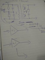
Last night at a gathering I asked Thorsten Loesch to recommend me an IV stage for my 9018 dac. The only way he knew he said that would sound good is ....and started drawing it on paper..see the attached..
So it is a step up transformer stage(to be followed by a 5867 tube or a lsk389 FET buffer). And it should be low voltages across those resistors.
He also stressed that the resistive loads should be connected to Vref and not ground....
As for the OTA opamp approach I also asked, he said that should work ok too...
Attachments
Goodmorning people
Back from a little break from the dac project where I have focused on my family, house and a OTL amplifier project which is allmost finished
But yesterday I tried a little with the dac, loads and the two step up's that I have.. And now the matter:
The unknown British step up is way off! Absolutely bad sound! No bas respond what so ever. Boring highs and midrange may be useful, but not in this application.. Bas respond got better by loading the dac with 1 ohm, but certainly not good enough!
BeyerDynamic TR/BV 370 215 006 : Sound quality was very good, but there was some serious phase problems!
It sounded like a kind of artificial surround or spatial stereo.
I don't know what seems to be wrong - Measurement 1 kHz 0dB said 65mV from one side of secundary and ground and about 105mV from other side of secundary and ground?
The phenomenon changed a bit when I took ground away from faraday shield pin and when I solder of the load resistors..
The tranni's haven't been used when I received them so I don't think they are non functional.
If there is anybody in here who know's how to load or treat these BeyerDynamic TR/BV 370 215 006 transformers, You should be welcome to share that info with me
Best from Henrik
Back from a little break from the dac project where I have focused on my family, house and a OTL amplifier project which is allmost finished
But yesterday I tried a little with the dac, loads and the two step up's that I have.. And now the matter:
And now for some interesting things.
Also yesterday I tried out 2 kinds of step up 1:15. No music only sine tones at 0dB.
A BeyerDynamic TR/BV 370.215.006 and an UnKnown british step up. Dac loaded with 1 ohm 1% resistors.
BD - 1000 Hz out: 137mV (both phases)
UK - 1000 Hz out: 139mV (both phases)
BD - 30 Hz out: 133mV (both phases)
UK - 30 Hz out: 27,9mV (both phases)
BD - 20 Hz out: 127mV (both phases)
UK - 20 Hz out: 18,3mV (both phases)
BD : 85ohm dcr 400mH pri. 10k dcr >200H sec.
UK : 20ohm dcr 10,8mH pri. 304 ohm dcr 17,6H sec.
As I said, I have not listened to music yet but something tells me that the BeyerDynamic will be the best regarding to bass respond even though I have loaded the dac with 1 ohm!
BTW is there some "easy" way to calculate input impedance the dac look into the various transformers? Typically, I am only aware of Dcr and ratio
The unknown British step up is way off! Absolutely bad sound! No bas respond what so ever. Boring highs and midrange may be useful, but not in this application.. Bas respond got better by loading the dac with 1 ohm, but certainly not good enough!
BeyerDynamic TR/BV 370 215 006 : Sound quality was very good, but there was some serious phase problems!
It sounded like a kind of artificial surround or spatial stereo.
I don't know what seems to be wrong - Measurement 1 kHz 0dB said 65mV from one side of secundary and ground and about 105mV from other side of secundary and ground?
The phenomenon changed a bit when I took ground away from faraday shield pin and when I solder of the load resistors..
The tranni's haven't been used when I received them so I don't think they are non functional.
If there is anybody in here who know's how to load or treat these BeyerDynamic TR/BV 370 215 006 transformers, You should be welcome to share that info with me
Best from Henrik
d it should be low voltages across those resistors.
He also stressed that the resistive loads should be connected to Vref and not ground....
This is thinking along straight "voltage" DAC application - is Thorsten just following convention - a convention that can not be broken for any other "voltage" DAC, other than the Sabre DAC. Also, in my view, offset current is preferable to offset voltage.
Sometimes rules needs to be broken, but only sometimes.
As for the OTA opamp approach I also asked, he said that should work ok too...
Done over a hundred of those with the Sabre DAC.
Cheers, Joe
.
Member
Joined 2006
Yeah..I am not sure if he had done anything exhaustive recently on the 9018 iv, as this chip is not in his current agenda I guess...
I did question him if I should use small resistive loads to get into deeper current mode..and he asked me to define it... He definitely knows it well but just doesnt care about using it under current or voltage mode I suppose...
BTW, is it ground or Vref that the loads should be connected to? Have you tried it on Vref?
As for the OTA, I recall hes the one.that first proposed the opa660 which I plan to try....a bit OT here, could you answer my question wrt ota in the other.thread? Thanks Joe
I did question him if I should use small resistive loads to get into deeper current mode..and he asked me to define it...
He definitely knows it well but just doesnt care about using it under current or voltage mode I suppose... BTW, is it ground or Vref that the loads should be connected to? Have you tried it on Vref?
As for the OTA, I recall hes the one.that first proposed the opa660 which I plan to try....a bit OT here, could you answer my question wrt ota in the other.thread? Thanks Joe
Last edited:
BTW, is it ground or Vref that the loads should be connected to? Have you tried it on Vref?
Only with opamps, but with OTA I would rather take it out of the equation. It's just another potential way of letting noise in - and in this instance less is always a plus as Vref is supposed to be a zero impedance reference, across a very wide bandwidth. Sorry, here I believe it to be a good thing to be suspicious.
Besides, using a zero feedback OTA, getting things to Ground makes sense in other ways, much easier as you don't have to get rid of +1.65V when you connect directly to OTA (off topic I know), which I do all the time.
But I don't want to come across all preachy, I just bring up the options for others to consider and they decide what suits them.
Cheers, Joe
.
Member
Joined 2006
Hi all,
how is possible to measure THD on a finished BII? What's the chain needed?
By a CLIO system or Arta based system is it possible?
By a CLIO is impossible to investigate over 20KHz (or 48KHz with Arta based PC) but the region to investigate about is located in the low part of the spectrum.
For a THD so low like that should be exhibited by a finished DAC, how is it possible to check the THD? I would like to check the real THD after the tranny, and after the tube stage so I have a real THD in hands.
And, but only later, the different THD for a (almost) "current mode" trafo connected outstage. Now I am with a (almost) "voltage mode" trafo connected, 300H primary inducatance and 20K load.
I read before, mainly at the beginning "check the THD" ... how can I do?
Thanks for any suggestion.
Ciao
Hi all,
how is possible to measure THD on a finished BII? What's the chain needed?
By a CLIO system or Arta based system is it possible?
By a CLIO is impossible to investigate over 20KHz (or 48KHz with Arta based PC) but the region to investigate about is located in the low part of the spectrum.
For a THD so low like that should be exhibited by a finished DAC, how is it possible to check the THD? I would like to check the real THD after the tranny, and after the tube stage so I have a real THD in hands.
And, but only later, the different THD for a (almost) "current mode" trafo connected outstage. Now I am with a (almost) "voltage mode" trafo connected, 300H primary inducatance and 20K load.
I read before, mainly at the beginning "check the THD" ... how can I do?
Thanks for any suggestion.
Ciao
Ether one should work fine. The area of your concern with transformer should be bellow 1 KHz. That will be much higher than the rest. With tube and transformer, you will be in much higher THD % than your audio interface or DAC itself. I would suggest to do frequency flatness test first to see if your transformer termination is correct. For that you should be able to measure higher than 20KHz. Ideally your DAC should have S/PDIF input. That way you could send signal out of your audio device, and than rout back to analog input of your device. I am saying that because I am not sure if on Windows you could have USB out and than analog in to a different device.
finally it is more simple than what somebody can think.
I used some traces from a test audio CD and I entered to the SPDIF input.
Works fine and it is possible by Clio or by Visual Analyser or similar to have THD, FFT and all the information needed to qualify the response of the ES9018.
Also by the oscilloscope only you have a raw info about the output under test.
What I discovered is the i2S interface is critical.
Going out from the USB of the laptop and entering to the Weiliang Xmos U8 I have always the left channel with distortion: I tried with 2 different PCs, same behaviour. I tried with different software players (same tracks) - foobar and jriver - and the behavioru is the same. I tried with some software tones generators. Same behaviour. The problem is the Weiliang U8 board. I changed the Weiliang U8 board (I have 3 of them) .... same behaviour.
Not happy, I tried going out from the USB and entered in a M2Tech, and I used its BNC SPDIF output, works fine for 44.1KHz of sample rate. Falls at 96KHz. But with M2Tech this is well known. Anyway finally I had 3 confirms the USB of the PCs is OK.
What i don't understand is how is possible for a Weiliang XMOS U8 USB interface to distort only one channel. Finally the data flux from the XMOS U8 to the ES9018 is a digital flux made of Word Clock, Left and Right Channnel mixed together plus the Clock. 3 "wires"
.... driver problems? the firmware of the Weiliang U8 board? On Monday I will try with an Amanero.
But now I am going out of this thread.
Finally, going back about how is it possible to test if the trannies works well, with some traces in a CD or in the HDD, play them by a player (computer or CD player) and an oscilloscope minimum, or some softwares to have the THD and FFT, it is possible to check if the trannies have almost a flat response and if there are big trouble to solve.
.... now I investigate about the i2S USB input where I have the troubles.
regards.
- Status
- This old topic is closed. If you want to reopen this topic, contact a moderator using the "Report Post" button.
- Home
- More Vendors...
- Twisted Pear
- Buffalo II & transformers