/cry
So the VA on the buffalo is drawing .66 amps and the VA wont go over 1.0V. I don't know what's wrong. edit: ya my long shot guess was wrong. The LCDPS works fine without load. The VD side is holding fine at 6.0V with the buffalo attached. I've tried switching sides with similar effect. I have to assume that something crazy is going on in the buffalo to make it draw that much current.
So the VA on the buffalo is drawing .66 amps and the VA wont go over 1.0V. I don't know what's wrong. edit: ya my long shot guess was wrong. The LCDPS works fine without load. The VD side is holding fine at 6.0V with the buffalo attached. I've tried switching sides with similar effect. I have to assume that something crazy is going on in the buffalo to make it draw that much current.
Re: /cry
Is this with an IVY connected?
How does it behave when on its own?
I would also check for shorts around the AVCC opamp.
chobint said:So the VA on the buffalo is drawing .66 amps and the VA wont go over 1.0V. I don't know what's wrong. edit: ya my long shot guess was wrong. The LCDPS works fine without load. The VD side is holding fine at 6.0V with the buffalo attached. I've tried switching sides with similar effect. I have to assume that something crazy is going on in the buffalo to make it draw that much current.
Is this with an IVY connected?
How does it behave when on its own?
I would also check for shorts around the AVCC opamp.
chobint said:IVY is not conneced, my first wild guess was that the IVY was shorting the ouput on the buffalo so i disconnected it last night
Ok, its probably best to post some pics and such on our support forum, so we don't add debugging noise to the thread.
Also check the orientation of the AVCC opamp.
Cheers!
Russ
closer inspection has potentially revealed a small solder bridge on IC1, looking further at opamp config
edit: opamp config looks fine. my camera will never capture this detail (cell phone) but the solder bridge looks to be between pins 2-3 and 4-5 from the bottom, on the left side of the chip if you are reading the text on it right side up. I have thoroughly blow/vaccuumed the boards to ensure no metal dust/fragments were on the loose, still hasnt helped. I'm not confident in this diagnosis however, since the buffalo's were all tested and solder bridges don't just jump out of the air. thanks
edit: opamp config looks fine. my camera will never capture this detail (cell phone) but the solder bridge looks to be between pins 2-3 and 4-5 from the bottom, on the left side of the chip if you are reading the text on it right side up. I have thoroughly blow/vaccuumed the boards to ensure no metal dust/fragments were on the loose, still hasnt helped. I'm not confident in this diagnosis however, since the buffalo's were all tested and solder bridges don't just jump out of the air. thanks
chobint said:okay, update again. The initial solder bridge problem has been fixed. The voltages seem fine now, the lock and automute lights work, but no sound. DIP's are low medium low medium
Are you using SPDIF input?
If so try setting all of the tri-state switches high(+).
Very sorry about the solder bridge, I think you must have got a board that Brian had to stencil manually and forgot to test before it went out. I am very sorry for the trouble.
Cheers!
Russ
sry I thought I've seen people asking about debugging on here before...
Anyway it's, I2s. I'll start a new post on tp site (http://www.twistedpearaudio.com/forum/default.aspx?g=posts&m=1466ֺ).
Anyway it's, I2s. I'll start a new post on tp site (http://www.twistedpearaudio.com/forum/default.aspx?g=posts&m=1466ֺ).
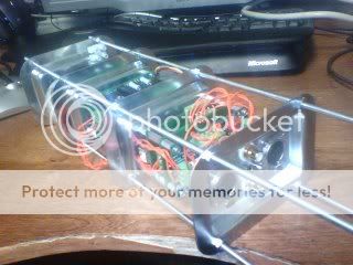
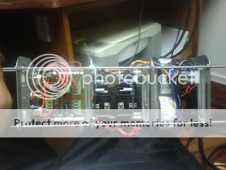
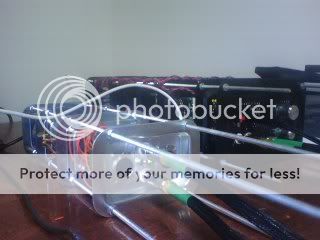
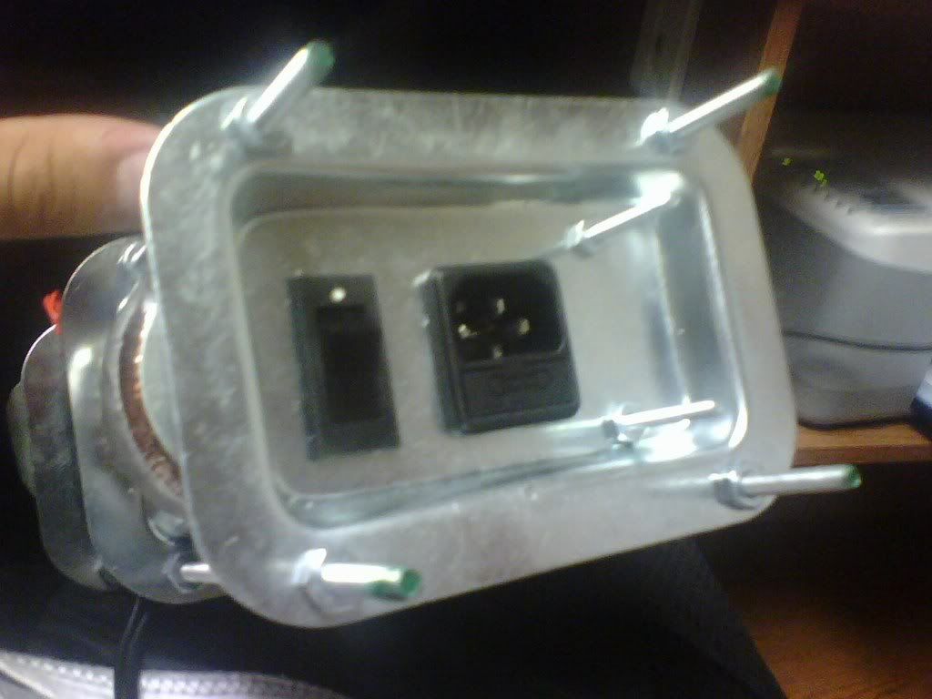
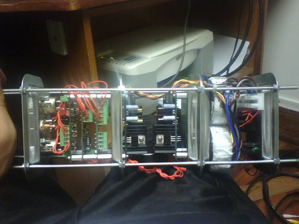
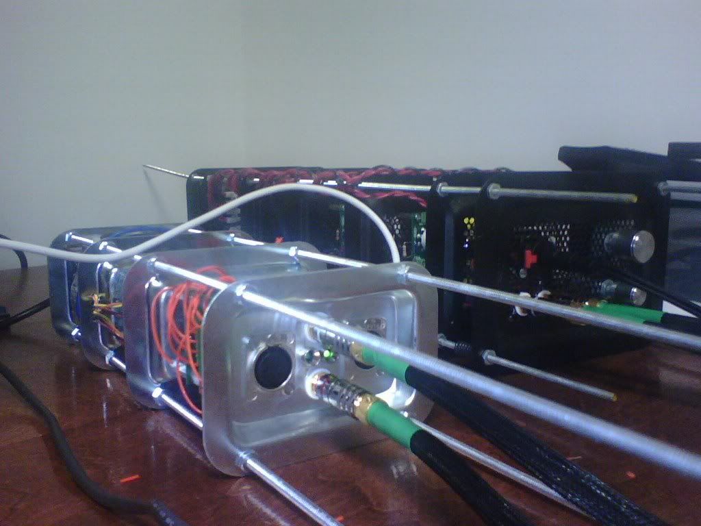
ITS ALIVE!!! well after some rough debugging, she's all boxed up and making sound. She's modeled after my Bijou as you can see in the last pic. The design worked out exceptionally well with Brian\Russ' stackable PCB's allowing for rediculously short signal paths. The whole thing is just slightly shorter than two consecutive dollar bills. The signal wires are going to need some shielding tho. Thanks tp guys.
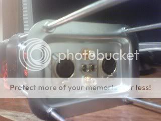

edit: ugh...I think I bought the wrong kind of XLR's
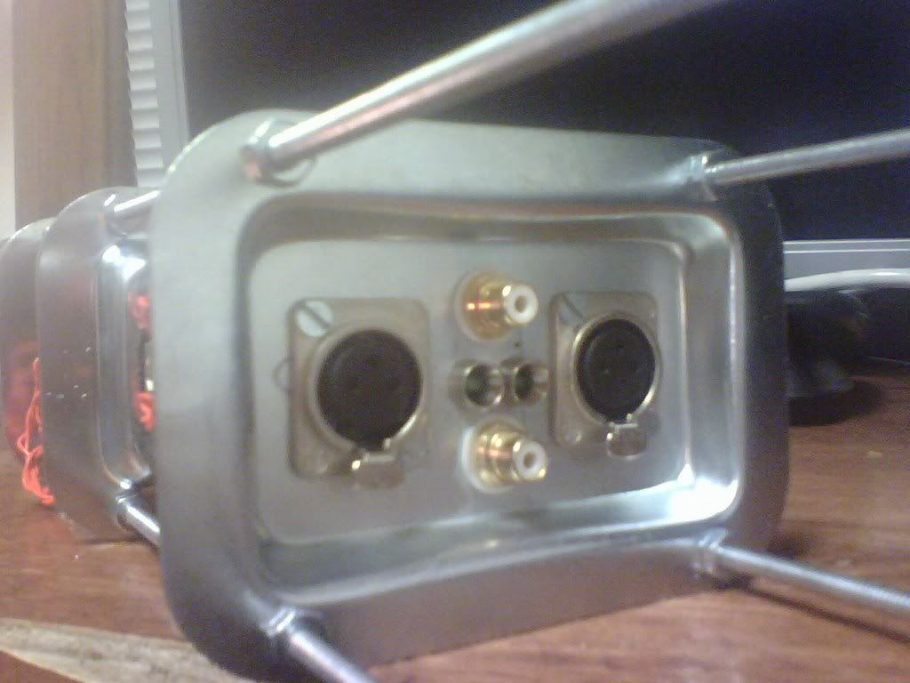
edit: ugh...I think I bought the wrong kind of XLR's
chobint said:ITS ALIVE!!! Thanks tp guys.
edit: ugh...I think I bought the wrong kind of XLR's
Very interesting project!
Yes, you should use male XLRs for output, but the good news is they will be easy to replace.
")
I hope you enjoy it!
Cheers!
Russ
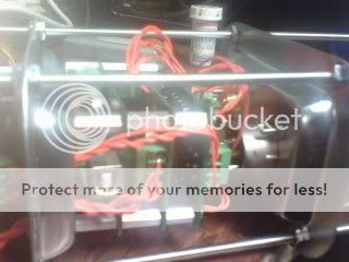
Interesting indeed. I have to ask, what ARE those plates for? 
I was wondering, assuming that they are ferrous (magnetic) steel alloy of some sort, if there might be any residual magnetic field problems with mounting a toroid on them?
Probably not, and all the field SHOULD be inside the toroid's core, but I thought there could be with some iron close to the windings. You could check by holding a plate close to a transformer while energized, and feeling for any vibration. Or, by measuring AC current, observing any increase.
Probably only a tiny fraction of possible loss there. Spacing it a 1/4" might eliminate altogether, and there may not be anything worth the effort. But I get nitpicky about things sometime. What do the experts who've been mounting power transformers like this think?
Well, I am not an E&M physics genious, but the chassis is grounded so it should work to block all the magnetic and various forms of EMF between plates. If someone could clarify the physics on that I'd be very grateful.
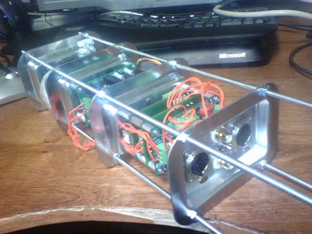
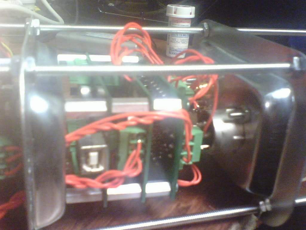
The concept originated from my Bijou amp, which was designed purely to look cool, or atleast look different.
The idea for the buffalo however is very performance minded, in that each type of energy is separated by a grounded plate. That is, the AC, DC, and audio sections of the amp are all shielded from eachother as to minimize internal interference. The concept is also based around the stacking nature of the PCB's. As previously mentioned, this design (as far as I can visualize) allows for the shortest possible signal paths without literally stacking all the components together.
So to answer your question is... the purpose of the plates is to allow for the shortest possible signal path while minimizing the interference between the power and signal sections of the DAC.
edit: and yes the plates are ferrous, as verified by the "does my magnetic screwdriver stick to this" test
edit2: and I lied the Buffalo didn't need shielded wiring, I just forgot to ground the case
Counterpoint Thread
Some of you folks may want to see this:
http://www.diyaudio.com/forums/showthread.php?s=&threadid=131149
Cheers!
Russ
Some of you folks may want to see this:
http://www.diyaudio.com/forums/showthread.php?s=&threadid=131149
Cheers!
Russ
BrianDonegan said:
Sorry about that. The last few that went out were a separate batch and I forgot IC4 for each of them. I'll send you IC4 tomorrow morning.
As for testing, I do that on a jig I made up, and use the uC header rather then the firmware on IC4. That's just the problem though. I did the testing, and just packed them up, forgetting the final step in my haste.
Brian
Thanks you for IC4. Installed and have the same problem with the comparator but now it works up to 96k. I would appreciate you and Russ looking at the probelm and sending out a working one at 176.4/192k via spdif.
This latest Buffalo just mutes when fed > 96k from an Apogee Big Ben and a 192k capable Pioneer Universal Player.
A friend of mine in Hong Kong has the same problem and so it looks like a comparator quality/design issue.
Unlike the last Buffalo, this one does not light up the auto mute led but allows noise to come through.
Fred
fmak said:
Brian
Thanks you for IC4. Installed and have the same problem with the comparator but now it works up to 96k. I would appreciate you and Russ looking at the probelm and sending out a working one at 176.4/192k via spdif.
Fred
Hello Fred,
Lately I have been using my new CS8416 MUX (because I have more than one source) then I2S into the Buffalo for all my listening. Using that combo I have no trouble doing anything up to 192khz.
There may indeed be some problem doing 192khz with the on-board comparator, but I don't see any obvious design problem. If anyone here has any ideas for part values to change etc I would be very grateful to see them.
Have you put this one to the scope to see if the output of the comparator is clean? It would be great if you could test at 44.1, 96, and 192khz.
I will try some tests with 192khz direct to the Buffalo SPDIF input when I get a chance. One problem I have there is my only 192khz source is AES output, not consumer level, so it will not be an apples to apples test. In the past I have simply bypassed the comparator with that source because the AES was already shifted up (in fact I had a 2:1 divider on it).
It may be that the current on-board comparator design is just not well suited to > 96khz SPDIF input. I2S input may simply be the better choice for > 96khz , or perhaps an external level shifter.
Once again, any advice is greatly appreciated.
In the short term. I can only suggest using a SPDIF receiver for >96khz SPDIF with I2S into the DAC.
Also I would appreciate any input Dustin may have as I am (I believe) using the same comparator SPDIF input section that he is using on his current evaluation board. I will write to him and see if he has any suggestions.
Cheers!
Russ
- Status
- This old topic is closed. If you want to reopen this topic, contact a moderator using the "Report Post" button.
- Home
- More Vendors...
- Twisted Pear
- Buffalo DAC (ESS Sabre 9008)