Posted this on TP site to, others might have some suggestons to?
Hi
My friend purchased a B3 insted of a B3SE by a misstake,
The solution now is to set the B3 in Stereo mode for stereo use.
There is no room for a sidecar or other extension cards so the Wawe Io need to be wired directly to B III
The source is a Wave Io directly wired to the B3 bord sending out I2S
All the steps in the Integration Guide for stereo operation has been performed but still no sound or lock light.
The wave io is working and playing music when tested on another B3SE.
I have placed the jumpers : JPCM1 JPCM2 and JPCM3 and placed the twelve jumpers J1-J12
I have set the SW2
I have good power in and out of all all tridents and 5.2v in on the B3.
Still no lock lock light or music.
Suggestions?
Last edited:
AVCC modulle removed for visual
This is a temp setup but worked perfect on my other B3SE
Will cleanup when things are working
https://goo.gl/photos/QNpPUUC85BQDLE9m9
.
This is a temp setup but worked perfect on my other B3SE
Will cleanup when things are working
https://goo.gl/photos/QNpPUUC85BQDLE9m9
.
Last edited:
Tested SW1 5 6 & 7 to off
SW2 8 both off and on
nu luck..
more pics..
https://goo.gl/photos/QNpPUUC85BQDLE9m9
.
SW2 8 both off and on
nu luck..
more pics..
https://goo.gl/photos/QNpPUUC85BQDLE9m9
.
Possible fault found,
On my working B3se the 1,2v trident sits at right
side ( when looking from top and power inn against me)
It is oposite om the non working B3.
Will switch soon,
Ideas if the 3,3v would have hurt the Buffalo 😶?
That would definitely keep it from working
")
As for damage, you will probably be okay, but I can't promise that. I have seen reversed Tridents before without damage.
Back again,
My bad, i was looking from the other end, the left become right....
The Tridens where at its correct pos and outputting the apropriate 1,2v and 3,3v.
The AVCC is outputing 3,5 at both channels.
The R4 for the 1,3v VDD is quite hot though.
it is a 1/4w thru hole resistor,
can hold my finger on it but it is not plesant.
Whitout doubt mutch warmer than the other R4 resistors.
Hmm..
Lower side:
Do the firmware contribute in any way regarding this probl?
The B3 is from 2013 ish.
Can i possibbly use the firware from the B3SE or opposite to test if the firmware has a bug?
https://goo.gl/photos/7jw3yofxK5SVAoPL7
.
Do the firmware contribute in any way regarding this probl?
The B3 is from 2013 ish.
Can i possibbly use the firware from the B3SE or opposite to test if the firmware has a bug?
https://goo.gl/photos/7jw3yofxK5SVAoPL7
.
Last edited:
Hi Brian.
I'm the friend that pellesmil is helping regarding the B3 problems.
I purchased the B3 from Twisted Pear Audio sometime between september and november 2011.
After to long time in a drawer, I will now try to finish my project, and looking forward to success with help from you!
I'm the friend that pellesmil is helping regarding the B3 problems.
I purchased the B3 from Twisted Pear Audio sometime between september and november 2011.
After to long time in a drawer, I will now try to finish my project, and looking forward to success with help from you!
Yepp.
After a lot of help from gwikse on a "sister forum" in Norway he came up with the idea of tracing power to the Crystec.
After some initial measurements the Lock light lit for first time
But how long was Adam in paradise....
The light went out after i touched the Chrystek.
After some investigation and check of the soldering i found out that the light goes on when pressing on right lower / nearest corner and goes dead when pressing on the left lower / nearest corner (this is when looking at the B3 with the PS down and the text the right way.
There is a low qlick sound (relay) when the light goes on and off.
What do you think, qould this be reapaired by means of my soldering iron (not by far the smallest compaired with thise parts ?........
https://goo.gl/photos/paagw3WAaet7KA2W9
Last edited:
I have been trying to assist pellesmil with troubleshooting his dac. He and I believe the crystek clock is damaged. He tried to figure it out on his own with a little assistance from me. And now he needs your input on how to proceed.
The clock is damaged. I do not know if there are other problems as well. And prior to swapping the crystek I though perhaps it would be a good idea to verify that the B3 is working if the clock is swapped out without actually swapping it out.
He has a working B3se that AFAIK can be used for this. If I am not mistaken, he can connect both the B3 and the B3se to the I2S source and connect the clock pins from the healthy B3se clock output to the corresponding header on the B3 and leave out the trident on the B3? If all else is ok, the B3 should lock as well as the B3se right?
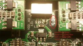
BUT. The picture he posted of the clock and the "5V" on the crystek output pin worry me. How is this possible? Where does the 5V come from? Is it related to the trident that power the crystek and eliminated as a possible issue if he remove the trident? Is this a sign of a damaged ESS chip? Is this just a matter of a Vin to Vout short on the trident or something like that?
Well, my suggestion is that he remove the trident. Measure the pin again, if there is still 5V there, well what then? Is it supposed to be like that? Come on. Fumbling around in the dark here....
The clock is damaged. I do not know if there are other problems as well. And prior to swapping the crystek I though perhaps it would be a good idea to verify that the B3 is working if the clock is swapped out without actually swapping it out.
He has a working B3se that AFAIK can be used for this. If I am not mistaken, he can connect both the B3 and the B3se to the I2S source and connect the clock pins from the healthy B3se clock output to the corresponding header on the B3 and leave out the trident on the B3? If all else is ok, the B3 should lock as well as the B3se right?
BUT. The picture he posted of the clock and the "5V" on the crystek output pin worry me. How is this possible? Where does the 5V come from? Is it related to the trident that power the crystek and eliminated as a possible issue if he remove the trident? Is this a sign of a damaged ESS chip? Is this just a matter of a Vin to Vout short on the trident or something like that?
Well, my suggestion is that he remove the trident. Measure the pin again, if there is still 5V there, well what then? Is it supposed to be like that? Come on. Fumbling around in the dark here....
Attachments
Last edited:
Sorry for our slow replies. Russ and I have both been slammed at out day jobs lately.
First, yes, that plan should work. Thanks for helping out.
Secondly, the 5V is troubling. There is no 5V anywhere near the XO. That is a GND pin, so I am guessing it was a mistaken measurement from the 5V input to the XO GND. If not, something very strange is happening.
First, yes, that plan should work. Thanks for helping out.
Secondly, the 5V is troubling. There is no 5V anywhere near the XO. That is a GND pin, so I am guessing it was a mistaken measurement from the 5V input to the XO GND. If not, something very strange is happening.
- Status
- This old topic is closed. If you want to reopen this topic, contact a moderator using the "Report Post" button.
- Home
- More Vendors...
- Twisted Pear
- Buffalo 3 not working in Stereo mode