I've been thinking about how to do a synchronous stereo mic measurement on a budget. I plan on using mostly what I have on hand and would like to use the PC's sound card. The mics need to be omni directional.
I have two reasons for needing this 1) a two driver near field synchronous measurement for phase issues, and 2) two measurements (aka binaural) separated by ear-ear distance for possible speaker equalization improvements.
I have two reasons for needing this 1) a two driver near field synchronous measurement for phase issues, and 2) two measurements (aka binaural) separated by ear-ear distance for possible speaker equalization improvements.
Last edited:
Fixture, PC line input and Mics
After some research on electret mics and low cost modules I've decided to start with the Adafruit-Max4466 Electret Microphone Amplifier - MAX4466 with Adjustable Gain ID: 1063 - $6.95 : Adafruit Industries, Unique & fun DIY electronics and kits
The mic capsule (includes FET) used is a CUI CMA-4544PF-W electret mic http://www.cui.com/product/resource/cma-4544pf-w.pdf , which is fairly flat and goes 20Hz-20Khz.
The preamp used is a Max4466 https://datasheets.maximintegrated.com/en/ds/MAX4465-MAX4469.pdf
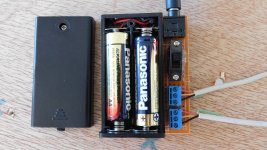
PC line level is around 1Vrms, depending on the definition you use, it could be +/-6db from this, but we'll use 1V. The preamp can go nearly rail-rail so it's convenient to use 2AA batteries for a +3VDC supply. The preamp output ref level is Vcc/2 . So we'll use 1.5VDC as Agnd for the line level and DC couple to the PC. This is convenient, so our output is +/-1.5pk Vac.
An on/off switch is included for battery power. The current draw for each module is ~25uA typical, and the line input impedance is ~10K (1Vrms/10K=100uA). Total is 2*25uA + 2*100uA = 250uA. The battery (cheap ones) have 1000mA-Hr capacity, and on a slow drain should last 1000mA/0.250mA=4000hrs. It'll probably self discharge before this")
The pics below show the fixture battery, line jack and wiring terminals.
After some research on electret mics and low cost modules I've decided to start with the Adafruit-Max4466 Electret Microphone Amplifier - MAX4466 with Adjustable Gain ID: 1063 - $6.95 : Adafruit Industries, Unique & fun DIY electronics and kits
The mic capsule (includes FET) used is a CUI CMA-4544PF-W electret mic http://www.cui.com/product/resource/cma-4544pf-w.pdf , which is fairly flat and goes 20Hz-20Khz.
The preamp used is a Max4466 https://datasheets.maximintegrated.com/en/ds/MAX4465-MAX4469.pdf
PC line level is around 1Vrms, depending on the definition you use, it could be +/-6db from this, but we'll use 1V. The preamp can go nearly rail-rail so it's convenient to use 2AA batteries for a +3VDC supply. The preamp output ref level is Vcc/2 . So we'll use 1.5VDC as Agnd for the line level and DC couple to the PC. This is convenient, so our output is +/-1.5pk Vac.
An on/off switch is included for battery power. The current draw for each module is ~25uA typical, and the line input impedance is ~10K (1Vrms/10K=100uA). Total is 2*25uA + 2*100uA = 250uA. The battery (cheap ones) have 1000mA-Hr capacity, and on a slow drain should last 1000mA/0.250mA=4000hrs. It'll probably self discharge before this
The pics below show the fixture battery, line jack and wiring terminals.
Attachments
Initial measurements
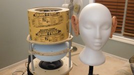
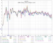
These are quick measurements, just to see how close I am.
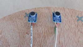
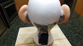
I'm using a calibrated UMIK-1 as a reference. The 3 mics are placed, in proximity (pic#1), and pointed toward a speaker 1m away. The FR amplitude variation is from mic position difference, the speaker and room acoustics. I just need roughly the same profile (whatever it is) on all 3 mics.
The 2 Adafruits measure remarkably close to each other (@<6KHz) and exhibit the same profile (@<6KHz) as the UMIK (also an electret).
The Adafruit module's filter is clearly visible at ~6KHz. I'd prefer a roll off around 16KHz or higher for a measurement mic. The CUI mic is capable of hitting 20KHz. The Max4466 has filter capability set by RC values, and it looks like I'll be changing that.
These are quick measurements, just to see how close I am.
I'm using a calibrated UMIK-1 as a reference. The 3 mics are placed, in proximity (pic#1), and pointed toward a speaker 1m away. The FR amplitude variation is from mic position difference, the speaker and room acoustics. I just need roughly the same profile (whatever it is) on all 3 mics.
The 2 Adafruits measure remarkably close to each other (@<6KHz) and exhibit the same profile (@<6KHz) as the UMIK (also an electret).
The Adafruit module's filter is clearly visible at ~6KHz. I'd prefer a roll off around 16KHz or higher for a measurement mic. The CUI mic is capable of hitting 20KHz. The Max4466 has filter capability set by RC values, and it looks like I'll be changing that.
Attachments
Freq response vs gain
The Adafruit has adjustable gain potentiometer. It seems all the effective adjustment range is at one end of the pot adjustment.
We'll try that to see if gain effects the 6KHz bandwidth. As you see in the graphs below, it does not. Changing the HF bandwidth will require a component change.
I also used a subwoofer to check the lower freq bandwidth and that is actually pretty good as it rolls off around 30Hz. In fairness my sub rolls off in that range so I can't tell if its the sub or the mic. In either case its low enough.
Attachments
Nice find! Any idea where the low pass filter is in the circuit?
Since I'm lazy, I would have probably just bought another Dayton Audio iMM-6 mic to make a stereo pair. But you have a nice, cheap solution right there. 
Since I'm lazy, I would have probably just bought another Dayton Audio iMM-6 mic to make a stereo pair.
But you have a nice, cheap solution right there. Nice find! Any idea where the low pass filter is in the circuit?
Yes, I just found the schematic and layout for it. Looks like there are 3 filters.
A HP@32Hz at the mic input, then another HP@16Hz at the op-amp, then a LP@6KHz in the feedback loop of the op-amp.
Since I'm lazy, I would have probably just bought another Dayton Audio iMM-6 mic to make a stereo pair.
Some would call "lazy" efficient. The least resources to the end result
The Dayton mic is low cost, however its just a capsule and requires a preamp. Most PC soundcards only have a single mic input. If you want 2 inputs you're stuck with using the LineIn stereo jacks, and you need line levels for that. I can get electret capsules for <$1, but I was lazy and didn't want to build a preamp.
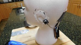
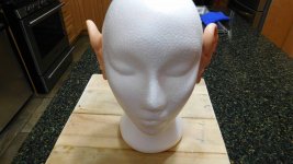
Head model stereo mic
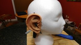
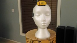
There is no better time for getting odd parts than near Halloween. There is a veritable bounty of foam heads and rubber ears (human, hobbit, elf, troll, demon, mice,... etc). Everything that's needed for a head model with stereo mics.
I have 2 equal omni mics, and all I need is the proper separation distance, and a couple of ears. I wonder if my EQ will be different / better?
I'm taking suggestions for the finishing touches [eg. hats, hair, ZZ-top beards, glasses, tattoo, alien eyes, fangs, etc.], I'm flexible. It has a stick (mic boom) for a body so no clothing please.
Attachments
Those are some big ears!
It will be interesting to learn what you come up with. Remember those funny ears aren't yours, and that makes a big difference. You should try with and without the ears. You'll run into some weird problems, like comb filtering and head shading, but you'll learn a lot.
It will be interesting to learn what you come up with. Remember those funny ears aren't yours, and that makes a big difference. You should try with and without the ears. You'll run into some weird problems, like comb filtering and head shading, but you'll learn a lot.
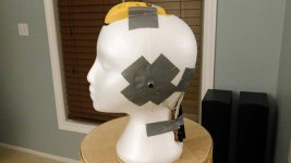
BigEar measurements
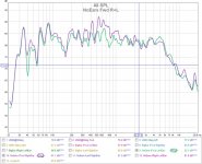
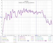
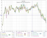
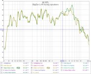
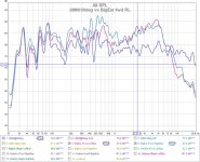
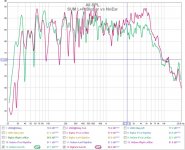
So, how does it measure up?
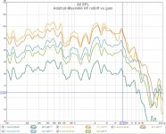
I need to modify the mic preamp boards (they still have that 6Khz LP), but before that I thought I'd run a few measurements and compare to a UMIK. Room acoustics, with both speakers driven and measuring at the listening position.
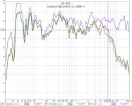
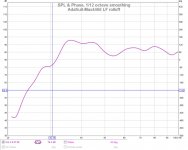
Looks like "no ears" wins as a stereo measurement system. The BigEar pinna's have an interested effect of boosting some of the mid band spectrum. Without the ear the mics look relatively flat. I wonder if that's why people prefer a downward sloped EQ?, especially if they have big ears
Enough fun, time to see if I can modify an SMT board.
So, how does it measure up?
I need to modify the mic preamp boards (they still have that 6Khz LP), but before that I thought I'd run a few measurements and compare to a UMIK. Room acoustics, with both speakers driven and measuring at the listening position.
Looks like "no ears" wins as a stereo measurement system. The BigEar pinna's have an interested effect of boosting some of the mid band spectrum. Without the ear the mics look relatively flat. I wonder if that's why people prefer a downward sloped EQ?, especially if they have big ears
Enough fun, time to see if I can modify an SMT board.
Attachments
-
 noears fwd RL.jpg131.5 KB · Views: 60
 -
 noears RL facing speakers.jpg131.8 KB · Views: 137
 -
 bigears fwd and turned R+L.jpg143.9 KB · Views: 136
 -
 bigear RL facing speaker.jpg134.4 KB · Views: 141
 -
 umik vs bigear fwd RL.jpg148.9 KB · Views: 142
 -
 umik vs angles.jpg145.2 KB · Views: 151
 -
 sum bigear vs noear.jpg150.6 KB · Views: 53
Removing the 6Khz LP
After getting the schematics for the Adafruit-Max4466, I thought I would just remove the one capacitor that creates the LP filter in the feedback loop. Then the op-amp would operate as high as it G-BW curve would take it. Hoping for stability. The sound source is a speaker with room acoustics. I only need relative measurements.
Checked the schematic, buzzed out the PCB to make sure I had the right component, removed the capacitor and tested (graph#1). well, it made virtually no difference. When I looked up the Max4466, its clear that it runs out of bandwidth even using the min 25x gain on the Adafruit. I would need to remove more components to get the gain down to 10x or so to get more bandwidth. To make matters worse, I need a 25ft cable on it (10pf/ft=250pf), and the extra load capacitance also causes a further drop in performance.
Software to the rescue. I created a cal file for REW using the UMIK as a reference. Graph#2 and #3 show the cal file used with and without the 6Khz LP filter. There is some variation as its hard to get the mics exactly back to the same spot.
Attachments
Last edited:
The Adafruit with mod and cal is doing better than I thought it would. I would have thought you'd get more noise up top. Can you check that, to see if the boost is adding a lot of noise above 6K?
Looks like the ears were fun, but giving you bad results. You learn something be trying stuff. I've used a "Junior" size soccer ball as a head substitute. It's about the right size. Full size puts the mics too far apart. A rugby ball might work, point upward.
After all my experiments, I ended up using the Moving Mic Technique for my room adjustments. There is a thread here about it.
I would have thought you'd get more noise up top. Can you check that, to see if the boost is adding a lot of noise above 6K?Looks like the ears were fun, but giving you bad results. You learn something be trying stuff. I've used a "Junior" size soccer ball as a head substitute. It's about the right size. Full size puts the mics too far apart. A rugby ball might work, point upward.
After all my experiments, I ended up using the Moving Mic Technique for my room adjustments. There is a thread here about it.
Sharp eye. Boosting the curve drags the distortion up. It's hard to measure noise in the environment I'm in. No free lunch here.
I wanted the CUI mic (20-20Khz) to show up in the FR curve with only a few dB of cal. Instead I'm cal'n out a 2nd order filter falling at 6KHz. Not what I wanted.
More mods coming....
I wanted the CUI mic (20-20Khz) to show up in the FR curve with only a few dB of cal. Instead I'm cal'n out a 2nd order filter falling at 6KHz. Not what I wanted.
More mods coming....
Attachments
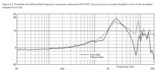
Those do not look like good windowed measurements. The response wiggles are from some nearby reflection. The peak with the "ears" is pretty typical.
Below is a Head and Torso with all the other modeled ear stuff measured from a flat acoustic source. You can see the peaking and resonances that are typical.
Your plots show a lot of promise. My experience with that class of mike have been good for this stuff. the big variation is sensitivity. The HF variations are there and they change with temperature and humidity. I would not concern myself is its within +/- 2 dB of your reference mike.
Summing the two microphones will get a lot of interference from the time delay differences between the two sides. If you can average the two plots it may be more useful. Keep in mine a head will modify the acoustic field around it a lot just being there.
Attachments
Those do not look like good windowed measurements. The response wiggles are from some nearby reflection. The peak with the "ears" is pretty typical.
Below is a Head and Torso with all the other modeled ear stuff measured from a flat acoustic source. You can see the peaking and resonances that are typical.
The measurements are not windowed because I was doing "relative" measurements to evaluate the mics. Any wide band sound field will do. I would window if I were doing speaker measurements.
Your plots show a lot of promise. My experience with that class of mike have been good for this stuff. the big variation is sensitivity. The HF variations are there and they change with temperature and humidity. I would not concern myself is its within +/- 2 dB of your reference mike.
Summing the two microphones will get a lot of interference from the time delay differences between the two sides. If you can average the two plots it may be more useful. Keep in mine a head will modify the acoustic field around it a lot just being there.
I summed the mics because I was looking for evidence of comb filtering due to the ear separation. When I get this working I was hoping to use the mics to try to minimize this effect from distance between the ears.
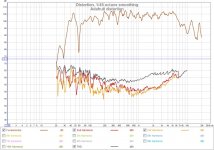
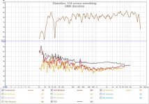
Finally got wide band from the mics.
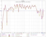
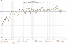
In post#12 I removed one filter and did not see an appreciable improvement in performance so I tried using a calibration file to flatten it. That worked but its not what I really wanted. I wanted full 20-20Khz from the module. So I'm back at it again.
Previously I missed an issue in the Adafruit-max4466 module. So there were actually 4 filters with new one (mic bias) that appears to be unintended.
1) mic bias filter (accidental input LP@6Khz)
2) mic DC removal HP@16Hz
3) opamp input HP@31Hz
4) opamp feedback LP@6Khz (it variable, gain dependant)
5) opamp gain-bandwidth product max4466
Removing C2 eliminates filter#1, removing C3 eliminates filter#4, turning down the gain to min (23x = +27db) allows the opamp to barely hit 20Khz addresses #5. The others (#2,#3) I can live with.
Now it works 30Hz-20Khz. The graph below is with no mic calibration from a speaker. I will eventually add some "minor" cal to flatten and SPL level the CUI mic curve. I should add that I tried both a 6ft (~60pF load) and a 25ft cable (250pF load) and there was no obvious difference.
Attachments
Last edited:
I should clarify the previous post. There are a few versions of the schematic for this module. If I use the schematic circa 2014, the capacitor C1 is on the mic bias (1 * 1K resistors) and the capacitor C3 is on the op-amp -ve feedback loop (parallel to gain adjust pot).
Last edited:
Calibration and aiming
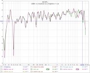
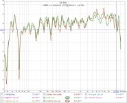
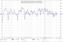
The previous mods increased the bandwidth of the Adafruit preamp.
Correcting residual differences and calibration was done by creating a REW calibration file and using a UMIK1 as a reference. The max4466 amp is not "clean" even on battery power and shows distortion increasing with frequency after 2KHz. The calibrated unit is shown with a UMIK1 in graph 1.
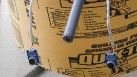
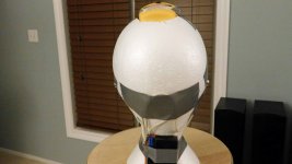
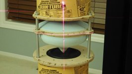
One problem with consistent measurements is positioning the mics. The distance is easy but repeatable aiming was accomplished using a "toy" laser level. It sells at the DollarStore or Dollarama (I forget which) for $3 CDN. It has 2 laser pointers that generate lines and is sufficient for this purpose. The pics show the foam head mounting of the mics and laser pointer aimed at a speaker.
The previous mods increased the bandwidth of the Adafruit preamp.
Correcting residual differences and calibration was done by creating a REW calibration file and using a UMIK1 as a reference. The max4466 amp is not "clean" even on battery power and shows distortion increasing with frequency after 2KHz. The calibrated unit is shown with a UMIK1 in graph 1.
One problem with consistent measurements is positioning the mics. The distance is easy but repeatable aiming was accomplished using a "toy" laser level. It sells at the DollarStore or Dollarama (I forget which) for $3 CDN. It has 2 laser pointers that generate lines and is sufficient for this purpose. The pics show the foam head mounting of the mics and laser pointer aimed at a speaker.
Attachments
- Status
- This old topic is closed. If you want to reopen this topic, contact a moderator using the "Report Post" button.
- Home
- Design & Build
- Equipment & Tools
- Budget stereo electret mic