Hi!
Yes, can be done, no problem with this, only a little heat dissipation in the dropping resistor or diodes.
Thomas
Use a 6.3V winding with a dropping resistor for the rectifier. (Experts: Is this practical?)......or diodes using the forward voltage drop?
Yes, can be done, no problem with this, only a little heat dissipation in the dropping resistor or diodes.
Thomas
Sorry for being MIA. I have been at work 7 days a week lately trying to catch up from a 15 day vacation. I also lost my primary Tubelab computer and have been preoccupied with making a new one.
I do not like the idea of using a heater winding for boost since as others stated there could be a possibility of an internal short inside the transformer putting line voltage into user accessible circuitry. I would use a small seperate transformer.
I have never used a James transformer, and I don't know how they are internally built. It seems that the heater windings are tapped for use at 5 or 6.3 volts. This would imply that they are insulated well enough for operation at +400 VDC or more for rectifier heater use. If this is true, the heater winding could be used for boost, but we have no way of knowing this for sure.
I would try using the James transformer as-is first. 350-0-350 will put the B+ at or over 400 volts which is plenty if not too much since heat can be an issue. Measure the DC voltage going INTO the heater regulator. If it is over 5.5 volts you should be OK.
MAny voltmeters, even some nice expensive ones, are rather inaccurate when the line voltage is distorted. I don't know how the power is in Israel, but 10% distortion or higher is common in the US. That's why I try to rely on the DC readings.
The 5AR4 should be OK with 4.75 volts on its heater. If it is too low then you can use the 6.3 volt tap with a resistor, provided that nothing else is connected to this winding.
The maximum input voltage spec for the Sharp regulator is 7 volts. I have not blown one from over voltage but I haven't gone beyond 7.5 volts. A diode dropping method might work using the circuit in post #14 but with 4 or 6 diodes. A simple resistor is not a good idea here since the voltage will rise to dead regulator levels if the tubes are removed.
I do not like the idea of using a heater winding for boost since as others stated there could be a possibility of an internal short inside the transformer putting line voltage into user accessible circuitry. I would use a small seperate transformer.
I have never used a James transformer, and I don't know how they are internally built. It seems that the heater windings are tapped for use at 5 or 6.3 volts. This would imply that they are insulated well enough for operation at +400 VDC or more for rectifier heater use. If this is true, the heater winding could be used for boost, but we have no way of knowing this for sure.
Don't boost anything; use the transformer as-is.
I would try using the James transformer as-is first. 350-0-350 will put the B+ at or over 400 volts which is plenty if not too much since heat can be an issue. Measure the DC voltage going INTO the heater regulator. If it is over 5.5 volts you should be OK.
I'm wondering about the accuracy of the voltmeter used to make these measurements.
MAny voltmeters, even some nice expensive ones, are rather inaccurate when the line voltage is distorted. I don't know how the power is in Israel, but 10% distortion or higher is common in the US. That's why I try to rely on the DC readings.
Use a 6.3V winding with a dropping resistor for the rectifier. (Experts: Is this practical?)......
The 5AR4 should be OK with 4.75 volts on its heater. If it is too low then you can use the 6.3 volt tap with a resistor, provided that nothing else is connected to this winding.
Use two 5V windings in series for around 9V into the filament regulator.
The maximum input voltage spec for the Sharp regulator is 7 volts. I have not blown one from over voltage but I haven't gone beyond 7.5 volts. A diode dropping method might work using the circuit in post #14 but with 4 or 6 diodes. A simple resistor is not a good idea here since the voltage will rise to dead regulator levels if the tubes are removed.
Even with three if none of them are true rms reading you are not getting an accurate picture of your AC voltage measurement. I have three different expensive meters and one cheap one. Guess which one I trust the least when I have a discrepancy even though it claims to have true rms capability. (And it almost always reads slightly lower than the others.)
Bear in mind as well that the cheap meters have poor accuracy specifications even with true rms conversion and may read several % high or low. DC accuracy is more easily attained in relatively cheap meters. If the meters perchance are identical then they should read pretty consistently even if wrong.
I would use the transformer taps exactly as intended - you should be close enough.
Even with three if none of them are true rms reading you are not getting an accurate picture of your AC voltage measurement. I have three different expensive meters and one cheap one. Guess which one I trust the least when I have a discrepancy even though it claims to have true rms capability. (And it almost always reads slightly lower than the others.)
Bear in mind as well that the cheap meters have poor accuracy specifications even with true rms conversion and may read several % high or low. DC accuracy is more easily attained in relatively cheap meters. If the meters perchance are identical then they should read pretty consistently even if wrong.
I would use the transformer taps exactly as intended - you should be close enough.
1) The cord extension set I used was faulty.
2) I used a better meter (more expensive).
3) The primary is 227V
4) HT 347V, 6.64V, 4.97V unloaded.
So... every thing seems to be OK, no need to do anything.

Thanks you all for the knowledge you posted here.

I'll proceed checking as describe in the manual.
As suspected. "Oh, oh! I have a problem!" ... its the meter.
Also note - the posted msg that said, "the voltages should only be 5% less, so therefore not a problem" remains correct. Even if the voltages are technically lower, it makes basically a 5% voltage difference overall - which is "0.95x" which if you take 20log(0.95) you get 0.44 dB. Which ... we all know ... is resolutely inaudible even to a trained ear, with average "program" music. 1 dB was chosen to be the smallest audible difference ... for a reason! Sure, there are people who can tell 0.6dB, and really good ones with pure tones that can figure out 0.3 dB, but that's under magical conditions. For "listening" outside an anechoic chamber, to more or less decent-but-not-ultimate tracks? 1 dB, and maybe higher.
GoatGuy
maybe I'm just used to measuring Hammonds.....
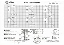
With 227VAC going into a 230V primary tap and no load, I would expect the HT and 5V to be a bit higher........the 6.64V filament winding looks reasonable.
The HT tap is rated at 350V at 350ma.
Ran: Do all of the 5V taps measure 4.97V unloaded?
3) The primary is 227V
4) HT 347V, 6.64V, 4.97V unloaded.
With 227VAC going into a 230V primary tap and no load, I would expect the HT and 5V to be a bit higher........the 6.64V filament winding looks reasonable.
The HT tap is rated at 350V at 350ma.
Ran: Do all of the 5V taps measure 4.97V unloaded?
With 227VAC going into a 230V primary tap and no load, I would expect the HT and 5V to be a bit higher........the 6.64V filament winding looks reasonable.
The HT tap is rated at 350V at 350ma.
Ran: Do all of the 5V taps measure 4.97V unloaded?
In the datasheet of the transformer it show that the HT tap in 350ma is 443DC.E.V ~ 313VAC or i don't read the spec right?
No i didn't measued all the tap, only the ones i connected to the board. i thought that if the reading with the cheap meter were the same so will the measurs with the expensive meter. (And because it was 00:30 so i was too tired)

I'll check them later.
Attachments
- Status
- This old topic is closed. If you want to reopen this topic, contact a moderator using the "Report Post" button.
- Home
- Amplifiers
- Tubes / Valves
- Bucking and boosting a tube power transformer