Well, it seems that I chose the worst combination for the regulated supply of my Class-D prototype input stage opamps: 6V8 zeners biased at 5mA (13uV noise).
The regulators are the typical NPN and PNP transistor configuration, whose bases go to the zener cathode (or anode for the negative rail, of course) and a series collector resistor to share power dissipation. A bias resistor goes from the HV rails to the zener cathode. This way I regulate the +/-50V rails to +/-6.3V. The zeners themselves are bypassed by a 100nF ceramic cap.
Do you think that changing to a lower noise zener (such as 5V6 that shows 2.9uV at 5mA) will noticeable suppose a lower noise floor at the audio output? I use NE5532 input opamps.
Thanks!
An issue with current sources
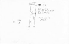
I don't understand what the fuss is about? The circuit below works very well, can be adjusted to cover most all situations and is a very cheap solution to boot. Upgrades would be to use single case matched pairs with the same current in both. This will give excellent results but is no longer as cheap. Of course the opposite sex is clearly possible.
This circuit with single case dual transistors will be better than using any other type of reference, including a band gap because it temperature tracks!
Roger
Attachments
Here we are discussing (at least I think so) voltage regulators, not current sources, although the current source has appeared when Eva recalled the test someone did to measure various zeners and LEDs noise. That guy used a constant current source for his tests.
What I have mentioned is a typical voltage regulator based on BJT + zener reference.
What I have mentioned is a typical voltage regulator based on BJT + zener reference.
A question of regulation
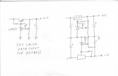
Sorry guys, too many late nights, too little sleep! The proper circuit would include a LM431 with adjustment and the feedback taken after the pass transistor. This makes a very good regulator and is quiet, unfortunately not useful for negative voltages.
A variation is to use it as a closed loop reference to drive a LM317, 337 pair. This also works very well. In this case a pair of 431’s are required.
The only trick of using the 431 successfully is to insure at least 10 ma through it and use a 10uf cap as local decoupling. The quality of this cap is of some importance as leakage will really upset things.
Roger
Attachments
This circuit with single case dual transistors will be better than using any other type of reference, including a band gap because it temperature tracks!
I agree that that current source is the best and most practical form, but it is not temperature stable. The Vbe of the top transistor is in the feedback loop and matters little, but the Vbe of the bottom transistor is outside of any feedback and drops at the usual 2mv/C, causing current to fall with rising temperature.
temperature tracking
Congratulations, you pass the test! I was wondering if anyone would question this.
I have used the circuit successfully as the temperature range it sees in my application is rather small and a decrease is good. In using it to drive an output stage in line level circuits it compensates nicely for the outputs change.
I don’t see an easy way to compensate it to track accurately. I was considering using a LM431 in place of the sense transistor with the adj pin used as the sense input. Of course the sense voltage would be a lot higher and would limit the maximum range a bit. In most applications I don’t see that as much of a problem. The reason I dropped it was because of the opposite sex problem with the 431. I sure wished they made a negative version!
Any one up for simulating it and trying stuff?
Roger
I think I've got the answer to a nontemperature dependant current source. Throw a schottky in series with the current sense resistor.
Using LTSpice with the standard 3904 and 1N5819 models, a 10v supply and a 10k bias resistor. I used a 470 ohm current sense resistor with my new CCS and trimmed the other current sense resistor to equal currents at 20C (597 ohm). I then did a temp sweep 0-100C.
Traditional Two Transistor CCS:
Current@Temp 0C: 1.17095ma
Current@Temp 100C: 0.817027ma
Change: 30.225%
My "New" CCS
Current@Temp 0C: 1.10152ma
Current@Temp 100C: 1.06516ma
Change: 3.301%
Thanks. Being just a teenage hobbiest at the moment, it's very encouraging to hear such things from a more experience designer.
P.S. You don't even have to give up a schottky diode drop of usable range, the diode just drops voltage otherwise seen by the current sense resistor (see attachment).
All you lose with this version is a dB or two of output impedance and 10 cents.
P.S. You don't even have to give up a schottky diode drop of usable range, the diode just drops voltage otherwise seen by the current sense resistor (see attachment).
All you lose with this version is a dB or two of output impedance and 10 cents.
Attachments
- Status
- This old topic is closed. If you want to reopen this topic, contact a moderator using the "Report Post" button.
- Home
- Amplifiers
- Class D
- Bruno Putzeys' reference UcD amplifier