Fuling said:
I use 150k input resistors simply because that´s what I use in my four channel tube amp, and since I´m going to use the same active crossover I want the impedance to match.
I think Tubes are somewhat different, must be higher
when comes to input impedance.
But most of us use CD-output from modern CD players
with output stage ( Op-Amps ) having fairly good drive possibilities of 10k - 22k ohm.
As I can control Volume in CD Player, with remote control
I, myself, need nothing in between Player - Amplifier.
This is also a good thing, as no device / part can make audio signal better in quality
.. whatever part you put into audio chain, there will be a degradation, more or very, very little.
But yet, anything you add, will take away some quality.
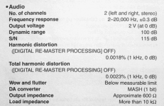
Attached is the output specification of my CD player:
Output Impedance: 600 ohm
Load Impedance: More than 10 kohm
Output level: Max 2 Vrms = CD standard
lineup
Attachments
Not even a little eq or tonecontrol?I, myself, need nothing in between Player - Amplifier.
I tried whitout them but...
")
These amps will be a part of a biamped system with active crossovers. The crossover has 30kohm stepped attenuators (well sort of, some kind of switchable voltage divider to adjust the output level)) on the outputs, so the input impedance of the power amps must be in above 100k.
I also want the amps to work together with passive preamps.
If the amps were connected to a proper preamp the whole input buffer could be removed and replaced with an input cap and a bias network.
I also want the amps to work together with passive preamps.
If the amps were connected to a proper preamp the whole input buffer could be removed and replaced with an input cap and a bias network.
okay, I see
I thought there were some good reasons for it.
It most often is, when people use such badly high input impedance.
From a purely electrical view point,
rather low value input resistor is good.
Remember that using for example 220 kohm
1volt / 220.000 = 4.5 uA
will be transfered in signal cable.
And at lower volume, maybe only 1/10 of this value = 0.4 uA
=================
And if we are talking in milliampere here, 30 mA .....
this will BE AS LITTLE AS ONLY :
0.0004 mA
=================
While, like me, using a lower value of resistor, 10 kohm
will allow more current to feed the input stage
1volt / 10.000 = 100 uA
and at lower volumes maybe: 10 uA
lineup doing the maths of currents in signal cables

I thought there were some good reasons for it.
It most often is, when people use such badly high input impedance.
From a purely electrical view point,
rather low value input resistor is good.
Remember that using for example 220 kohm
1volt / 220.000 = 4.5 uA
will be transfered in signal cable.
And at lower volume, maybe only 1/10 of this value = 0.4 uA
=================
And if we are talking in milliampere here, 30 mA .....
this will BE AS LITTLE AS ONLY :
0.0004 mA
=================
While, like me, using a lower value of resistor, 10 kohm
will allow more current to feed the input stage
1volt / 10.000 = 100 uA
and at lower volumes maybe: 10 uA
lineup
doing the maths of currents in signal cables Also: higher frequency -> need more current
Compare to fast digital signals, often use these values
to transport in digital signal cables:
0volt - 5volt .... into 50 Ohm
5/50 = 100 mA transported!
The Rule is:
The higher the frequency, the more current you will need
If having high freq troubles or high freq missing, could very well be
that there is TOO LITTLE CURRENT ( = to high impedance )
somewhere.
lineup
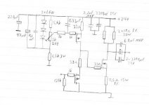
audio rules collectionFuling said:The schematic, exactly as built.
Some details could definitely be improved, but I built with parts I had at home and it seems to work perfectly fine:
Fuling
I think you should connect speaker between output and +V .
I think you should connect speaker between output and +V
Are there any benefits?
Thanks!
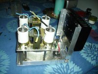
I strongly believe in CLC och LCLC filtering whenever quiet power supplies are needed. I got a bunch of these chokes from a surplus store a couple of years ago and I think 25mH will be more than enough to make this amp completely silent.
After the CLC filter comes this IRFP260-based capacitance multiplier, I need to drop a few volts and, most important, have a slow startup to avoid damaging my speakers.
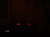
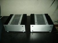
I finally got some top plates on these babies:
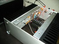
Now when they are finished I realize that cascoding the output stage probably would improve things quite a bit (not that they don´t sound marvellous as they are) but ripping them apart and changing the circuitry would be too much work.
There´s also a risk of damaging the threadings by removing and reinserting the bolts too many times and i DON`T want that to happen (again...).
The PSU remains unfinished since I´ve been doing a lot of prototyping and started (and almost finished) a X-Soz project simultaneously.
Once the X-Soz gets finished I´ll hook everything up in an nice and hot biamped setup 
Now when they are finished I realize that cascoding the output stage probably would improve things quite a bit (not that they don´t sound marvellous as they are) but ripping them apart and changing the circuitry would be too much work.
There´s also a risk of damaging the threadings by removing and reinserting the bolts too many times and i DON`T want that to happen (again...).
The PSU remains unfinished since I´ve been doing a lot of prototyping and started (and almost finished) a X-Soz project simultaneously.
Once the X-Soz gets finished I´ll hook everything up in an nice and hot biamped setup
Attachments

- Status
- This old topic is closed. If you want to reopen this topic, contact a moderator using the "Report Post" button.
- Home
- Amplifiers
- Pass Labs
- Brother-in-law of Zen