I read the app note, built a gainclone, then talked with an engineer at National's Overture group.
I may well be fast in lining up with what he said, since I have yet to build a bridgeclone both with and without the servos.
I choose to rely on his advice until I do, which was that the servos result in a lower noise floor and reduce the extreanous current flowing between the amps, and that using the precision resistors alone was for those lacking the money or desire to use them.
Bridge/paralell w. input-trafo
Please help with suggestions; my bridge/paralell (inveting input) "clone" have some slight distortion-issue.
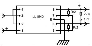
Probably because of the trafo-input (LL 1540) http://www.lundahl.se/pdfs/datash/1540.pdf
that I use for signal-splitting.
Any good suggestions on this?
ArneK
Please help with suggestions; my bridge/paralell (inveting input) "clone" have some slight distortion-issue.
Probably because of the trafo-input (LL 1540) http://www.lundahl.se/pdfs/datash/1540.pdf
that I use for signal-splitting.
Any good suggestions on this?
ArneK
Bridge/paralell w. input-trafo
Hi!
I first tried a "direct connection" from a balanced source, but this had too high signal level.
And then I used the LL1540 for splitting/balancing a single-ended signal.
But I think there must be a impedance-mis-match or something.
I'll hook up my scoope later.
Arne K
Hi!
I first tried a "direct connection" from a balanced source, but this had too high signal level.
And then I used the LL1540 for splitting/balancing a single-ended signal.
But I think there must be a impedance-mis-match or something.
I'll hook up my scoope later.
Arne K
Attachments
Re:Bridge/paralell ...
Hi!
I use a separate (active) pre-amp.
it's connected as on post 9, http://www.diyaudio.com/forums/showthread.php?postid=161559#post161559
without the op-amps, but with the LL1540.
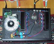
I use a 2 x 24V trafo, 600VA, dual bridges and 2 x 10 000uF PSU,
and every chip is bypassed with a 100uF Elna cap.
Trafo is connected as previous pic, with 33k as R/2 (x2).
Anyway, it seem to sound much better this morning, have left it on over night! (Maybe it is a "burn-in" issue).
Arne K
Hi!
I use a separate (active) pre-amp.
it's connected as on post 9, http://www.diyaudio.com/forums/showthread.php?postid=161559#post161559
without the op-amps, but with the LL1540.
I use a 2 x 24V trafo, 600VA, dual bridges and 2 x 10 000uF PSU,
and every chip is bypassed with a 100uF Elna cap.
Trafo is connected as previous pic, with 33k as R/2 (x2).
Anyway, it seem to sound much better this morning, have left it on over night! (Maybe it is a "burn-in" issue).
Arne K
Re: Re:Bridge/paralell ...
Well, if it sounds OK now great - otherwise perhaps you could check the DC offsets and work out how much current each pair of chips is sinking. If DC offset is more more than a few millivolts it might be worth zeroing each chip with a 50k multi turn pot on the non-inverting i/p
also have you thought to reduce the gain of the pre-amp and dispense with the transformer ? or if you keep it make sure there is no dc offset on the transformer i/p - they generally do not like DC atall ( not even a little bit )
cheers
mike
Cobra2 said:
Anyway, it seem to sound much better this morning, have left it on over night! (Maybe it is a "burn-in" issue).
Arne K
Well, if it sounds OK now great - otherwise perhaps you could check the DC offsets and work out how much current each pair of chips is sinking. If DC offset is more more than a few millivolts it might be worth zeroing each chip with a 50k multi turn pot on the non-inverting i/p
also have you thought to reduce the gain of the pre-amp and dispense with the transformer ? or if you keep it make sure there is no dc offset on the transformer i/p - they generally do not like DC atall ( not even a little bit )
cheers
mike
Re: Re: ....Bridge/paralell ...
The good news, It sounds good now!
DC-offset out (without load) less than 20mV
DC-offset input ; less than 5mV.
I have added a pair of 100nF to the PSU, (without believing that it would do much difference), run it "hard/hot" for a period, let it cool down, and started to listen to it.
My impression now, is that it is very "correct", a bit dry, but with a slight forward soundstage. Imaging/3D is rock solid.
But it has nowhere the sheer guts and power of my N-channel-amp, not as liquid and musical...but for the price...and parts-count...I'll say I'm happy.
Arne K
I wonder it bridged or paralelled can ever sound as good as single chips ?
I had good results with balanced.
When I tried paralelled without knowing quite why I could hardly bear to listen to it ! ( but I did not zero the o/p's )
( I have not tried balanced & paralelled )
Now I am running with a single chip per channel and I feel that this is the best sound that I have acheived.
I may be deluded, but if you don't find the sound quite delightful & engaging, I get the feeling that you may not be in the 'gainclone zone'") Do you really need all that power ?
Do you really need all that power ?
I wonder what others have found with this comparison
mike
I had good results with balanced.
When I tried paralelled without knowing quite why I could hardly bear to listen to it ! ( but I did not zero the o/p's )
( I have not tried balanced & paralelled )
Now I am running with a single chip per channel and I feel that this is the best sound that I have acheived.
I may be deluded, but if you don't find the sound quite delightful & engaging, I get the feeling that you may not be in the 'gainclone zone'
Do you really need all that power ?I wonder what others have found with this comparison
mike
Re: Re: Re: ....Bridge/paralell ...
Koinichiwa,
A small point of criticsm and also perhaps a little bit of explanation as to the "why" of the sound you describe. It seems you have literally "Bridge/Paralleled" multiple gainclones, including the local 1,000uF Caps et al. Such an approach leads invariably to problems with grounding.
I would recommend to change the grounding as follows:
1) Local 1uF/100V capacitors from +V to -V to guarantee stability, without effecting the ground routing.
2) PSU Capacitors should have a value of appx n X 1,000uF where n is the unber of chips used in the parallel/bridge system (up to 8pcs per channel can make sense) and the transformer(s) per channel (2 pcs of PSU Capacitors per channel, plus minimum 1 Transformer per channel, channels galvanically separate) should have a (total for several transformers series/parallel in low flux connection) n X 160VA power. So in your specific case I'd suggest a pair of 600VA+ transformers (one per channel) plus one pair of 3,900...4,700uF/50V main PSU Capacitors, look for low impedance and low inductances (ESR & ESL).
3) Power "Star Ground" where the supplies and PSU Capacitors meet. Seperate Input "Star Ground" where the input transformer centertap (if present) and the components from all the positive chip inputs are combined, a single wire links this to the "Kelvin Return" point of the power "Star Ground".
4) Starwire the positive and negative PSU lines to the chips using ideally twisted pairs of reasonably heavy wire, do NOT buswire the +V and -V lines.
5) If you MUST share the PSU between channels then have per channel a "input star", linked back individually to the kelvin return (the point of all flowing currents is zero) and double to quadruple the values of the PSU Capacitors, plus of course fit the biggest suckah of mains transformer you can possibly find.
You may find the results of such a rewire as suggested above rather greater than you would credit. Much (40 - 50% IMNSHO) of the sound of Solid State Amplifiers (or indeed other Amp's) is the result of correct ground routing. To put it simple, always think in loops traversed by the currents, the whole concept of "ground" in itself is highly dubious and letting yourself think that "ground is ground" rather than "ground is a convenient abstratcion" is the road to troubles.
Sayonara
Koinichiwa,
Cobra2 said:My impression now, is that it is very "correct", a bit dry, but with a slight forward soundstage. Imaging/3D is rock solid.
But it has nowhere the sheer guts and power of my N-channel-amp, not as liquid and musical...but for the price...and parts-count...I'll say I'm happy.
A small point of criticsm and also perhaps a little bit of explanation as to the "why" of the sound you describe. It seems you have literally "Bridge/Paralleled" multiple gainclones, including the local 1,000uF Caps et al. Such an approach leads invariably to problems with grounding.
I would recommend to change the grounding as follows:
1) Local 1uF/100V capacitors from +V to -V to guarantee stability, without effecting the ground routing.
2) PSU Capacitors should have a value of appx n X 1,000uF where n is the unber of chips used in the parallel/bridge system (up to 8pcs per channel can make sense) and the transformer(s) per channel (2 pcs of PSU Capacitors per channel, plus minimum 1 Transformer per channel, channels galvanically separate) should have a (total for several transformers series/parallel in low flux connection) n X 160VA power. So in your specific case I'd suggest a pair of 600VA+ transformers (one per channel) plus one pair of 3,900...4,700uF/50V main PSU Capacitors, look for low impedance and low inductances (ESR & ESL).
3) Power "Star Ground" where the supplies and PSU Capacitors meet. Seperate Input "Star Ground" where the input transformer centertap (if present) and the components from all the positive chip inputs are combined, a single wire links this to the "Kelvin Return" point of the power "Star Ground".
4) Starwire the positive and negative PSU lines to the chips using ideally twisted pairs of reasonably heavy wire, do NOT buswire the +V and -V lines.
5) If you MUST share the PSU between channels then have per channel a "input star", linked back individually to the kelvin return (the point of all flowing currents is zero) and double to quadruple the values of the PSU Capacitors, plus of course fit the biggest suckah of mains transformer you can possibly find.
You may find the results of such a rewire as suggested above rather greater than you would credit. Much (40 - 50% IMNSHO) of the sound of Solid State Amplifiers (or indeed other Amp's) is the result of correct ground routing. To put it simple, always think in loops traversed by the currents, the whole concept of "ground" in itself is highly dubious and letting yourself think that "ground is ground" rather than "ground is a convenient abstratcion" is the road to troubles.
Sayonara
Re: Re: ....Bridge/paralell ...
I have now made a few adjustments; split supply to 2x +/-10 000uF banks (one pair of caps pr. channel), and beefed up "ground-path".
(The local caps are "just" 100uF/63v Elna...)
It made it feel a bit more "bottom-solid".
Anyway, the sound is good enough for my mate ;-)
For myself, (if I make another for myself) I would do the suggested star-wiring thruout, larger heatsinks, and double trafos (or as mono-blocks).
And yes, my large living-room, and my AudioVector S-6 soaks power!
Arne K
P.S.: Thanx for your input !
Re: Re: Re: ....Bridge/paralell ...
Koinichiwa,
Just another note, it seems you are using the Transformer 1CT : 1CT.
You CAN change that to 1CT:0.5 (or better 2:1) which will reflect around 40K input impedance and may be an easier load to preamplifiers (SE or Balanced) while reducing gain by 6db.
Simply link 6/7 and 5/8 on the Transformer, 5/8 drives the Chips that supply the "Black" (negative) speaker terminal, 6/7 drive the chips that supply the "Red" (positive) speaker terminal.
In this case the input to the Chipamps is "floating Balanced", giving an effective DC Resistance to (sort of) ground for each Chip of around 18k, so the resistors from the non-inverting input to ground (if used) should be in the same region.
Sayonara
Re: Porcupine...err...BridgeClone
More caps & tweaks later....
I'm still wondering about impedance & gain...
Changed positive input resistors, and ended up with 4,7k ( to gnd), same as neg. input resistors. 220K feedback, 0,1R output.
Changed/inverted phase on one channel, (as I wanted to keep the 600VA trafo, and not buy 2 new ones), this helped a bit, bass seems tighter & more controlled now.
But the "fun" started when I used balanced input from a "Pro" Rane BB 44x, RCA to XLR converter with the increased gain this gave.
So-far, IMO, it seems that these amps can be set up w. a lot more gain than most articles describe.
Arne K
Re: My BC is too hot?
Have you checked the values over the current sharing resistors? If so what is the current flowing at idle?
Cobra2 said:I think something does not "add up", it's fairly warm,(~35ºC) just ideling.
No oscillation, (on scope or freq.counter) and less than 15mV DC-offset.
Any advice, please ?
Arne K
Have you checked the values over the current sharing resistors? If so what is the current flowing at idle?
Re: Re:....
That's like 15 W idle then...
Cobra2 said:0,015V over resistor on one pair, & 0,005V over another pair...
I guess these chip's are of the +/-10% variety....
So I would need trimpots for offset-null ?
Arne K
That's like 15 W idle then...
Re: Re:....
Maybe so.
One thing that puzzled me when I saw Jeff Rowland's amp using 3886 on his power amp, were the trimpots you can see on every chip.
Maybe he's using an inverted circuit on each chip and nulling offset on every one with the pot.
I can think of any reaso why he would use a pot on a non-inverting arrangement. Do you?
Carlos
Cobra2 said:
So I would need trimpots for offset-null ?
Maybe so.
One thing that puzzled me when I saw Jeff Rowland's amp using 3886 on his power amp, were the trimpots you can see on every chip.
Maybe he's using an inverted circuit on each chip and nulling offset on every one with the pot.
I can think of any reaso why he would use a pot on a non-inverting arrangement. Do you?
Carlos
- Status
- This old topic is closed. If you want to reopen this topic, contact a moderator using the "Report Post" button.
- Home
- Amplifiers
- Chip Amps
- Bridgeclone