pro said:Why the deviders on the two servos are different?
Peraps you have corrected only one, or it's so?
yeah, i corrected only one of them in hurry....
thanks
Attachments
Do you have full control over the feedback. It seems that you have made some errors there.Roushon said:
yeah, i corrected only one of them in hurry....
thanks
The design is pretty much alike mine....
peranders said:
Do you have full control over the feedback. It seems that you have made some errors there.
The design is pretty much alike mine....
Are you meaning about the t-network feedback? I do not understand you well. If you find any error please point out. I have not tested the circuit yet as clearly mentioned and warned anybody to build it. Also I already said before in this thread that I got help (directly or indirectly) from you too. But obviously the circuit is different from any circuit I have seen in the net.
peranders said:Yes, why have you design in the T-network?
It was suggested by Franz G. And I read in some site (which also acknowledges Franz) that it will sound better. I have no idea because I have not experimented with it. In the PCB I will have both the options (with or without t-network)
the suggestions is here
http://www.diyaudio.com/forums/showthread.php?postid=512184#post512184
http://www.diyaudio.com/forums/showthread.php?postid=512184#post512184
people may (or may be not) be wandering what happend to the pcb design and construction of my gainclone project in this thread. unfortunately i packed my baggage from india and now dropped in duesseldorf, germany learning german. from june i will be in muenster for a long time.
any friend out there from germany and preferably from muenster who can help me continue my hobby here in germany.
roushon.
any friend out there from germany and preferably from muenster who can help me continue my hobby here in germany.
roushon.
When you finally get back to working on this:
I think it would be better for you to use 1 buffer chip for both parrallel amps because any difference between any resistors, or the OPAs themselves will cause the 2 amps to "fight" each other which makes extra heat, and may be part of the reason that parrallel chips have a bit more distortion.
as mentioned before, match all the components for the 2 amps as well as you can. (i brough my multimeter into the electronics shop once to do this, they did not seem to mind") )
)
and buy both of the chips at the same time, hopefully from the same tube so they are likely to be manufactured right after each other.
I think it would be better for you to use 1 buffer chip for both parrallel amps because any difference between any resistors, or the OPAs themselves will cause the 2 amps to "fight" each other which makes extra heat, and may be part of the reason that parrallel chips have a bit more distortion.
as mentioned before, match all the components for the 2 amps as well as you can. (i brough my multimeter into the electronics shop once to do this, they did not seem to mind
)and buy both of the chips at the same time, hopefully from the same tube so they are likely to be manufactured right after each other.

the pcb
The pcb design of the project (parallel of two inverted LM3886) in this thread is below. The circuit design is already here, so I am not attaching again. But the parts value may be little different in the PCB, without any harm.
This is the first time I am making a PCB for amplifier, so expecting there will be mistakes. Please give me your suggestions, corrections or comments. This is important for me.
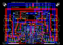
gmphadte said:On quick look...
Too much crowd near the heatsink. Capacitors don't appreciate heat.
Single PTH for power is a small conductor.
Grounding is not well done. Look at GND and OUT Gnd
Gajanan Phadte
Thanks. I will move the capacitors away from the heat sink. I am trying to avoid the PTH for power, or place more PTH closeby. About grounding, should I take the out-gnd from near the amplifier section? I do not understand what you mean.
Roushon.
- Status
- This old topic is closed. If you want to reopen this topic, contact a moderator using the "Report Post" button.
- Home
- Amplifiers
- Chip Amps
- Bridge or Parallel?