I'm repairing this amp for a friend. But I've read online that brax amps have life time warranty with no worries about new owner. I notice it doesn't have a serial number so i guess sending it to the manufacture is out of the question.
My friend stated that his brother hook the power backwards and smelled something burning. Then never cut on.
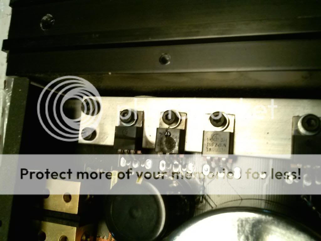
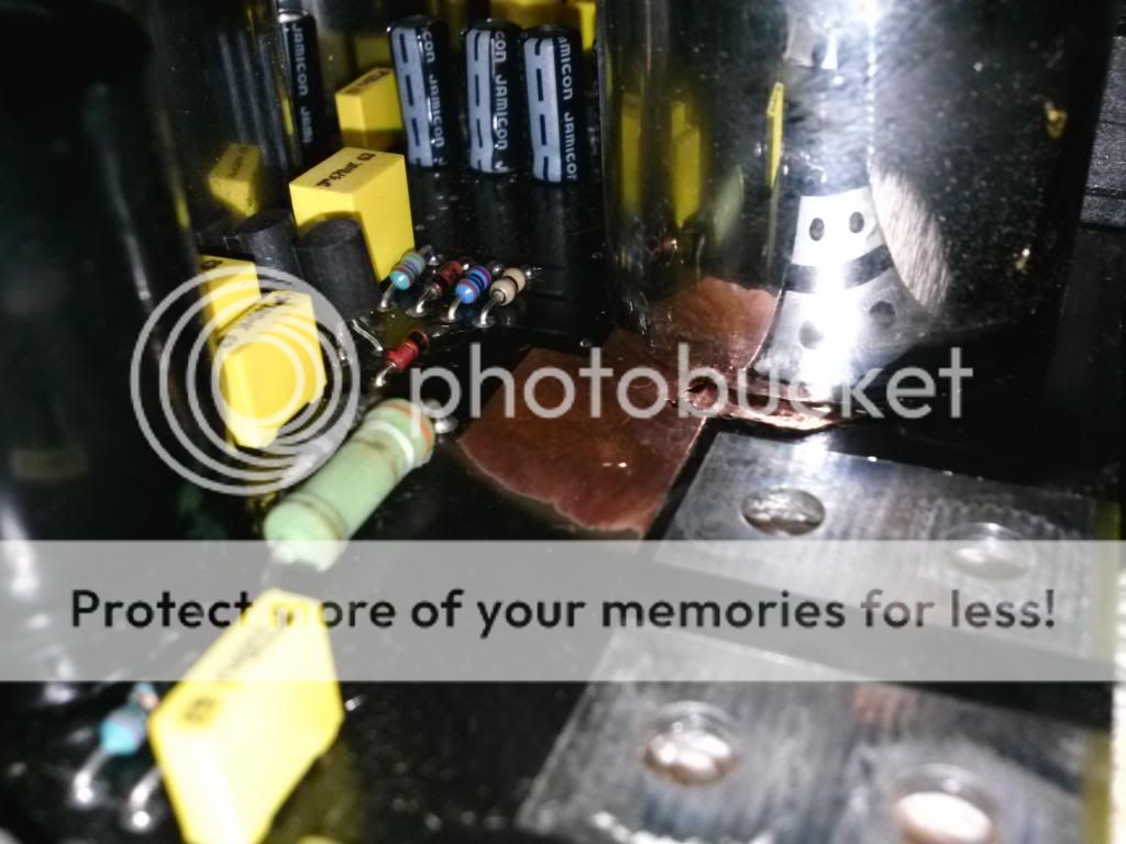
Once i opened it i notice that the ground trace on the power stabilizer terminals shorted and the copper trace is lifted from the pcb. Three if the six power fets are obviously blown.
Any thing else i need to check before ordering fets and trying to fix the ground trace?
Thanks in advance.
My friend stated that his brother hook the power backwards and smelled something burning. Then never cut on.
Once i opened it i notice that the ground trace on the power stabilizer terminals shorted and the copper trace is lifted from the pcb. Three if the six power fets are obviously blown.
Any thing else i need to check before ordering fets and trying to fix the ground trace?
Thanks in advance.
Last edited:
Thanks Perry, I've read your tutorial (got the full version) and successfully repaired a few with the help of Cecil and yours.
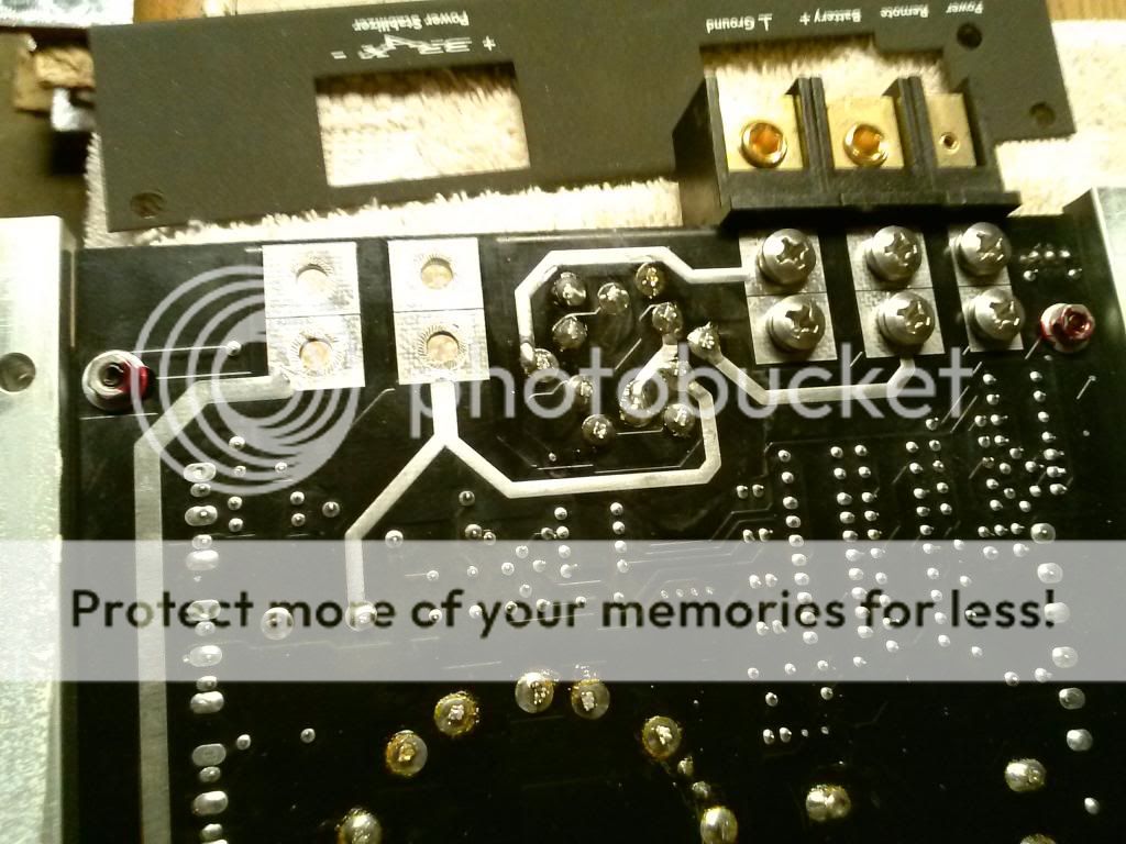
I planned on replacing all the fets. I'll check the drivers, i can't find the owners manual any where, I'm assuming the power stabilizer terminals are for some sort of capacitor (brax, duh,lol) but is it needed when powering up? Its just tied to the power input terminals, besides the ground since shorted/opened.
I planned on replacing all the fets. I'll check the drivers, i can't find the owners manual any where, I'm assuming the power stabilizer terminals are for some sort of capacitor (brax, duh,lol) but is it needed when powering up? Its just tied to the power input terminals, besides the ground since shorted/opened.
If the terminals for the stabilizer are directly connected to the power and ground terminals, you're likely correct and it's for a cap. An external cap shouldn't be required for the amp to work properly.
If the amp has a reverse-protection diode, you should check it as well.
If the amp has a reverse-protection diode, you should check it as well.
It fluctuates around 300 ohms on the casing. So am pretty sure its cosmetics. But that's where my damage trace is, right below the casing.
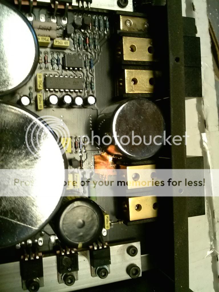
I don't see any rp diode by the power inputs. Check out the pics hopefully you can make out why it has a transformer between the power input and the power stabilizer terminals.

Perry feel free to save my pics for your tutorial. If you need more let me know.
I don't see any rp diode by the power inputs. Check out the pics hopefully you can make out why it has a transformer between the power input and the power stabilizer terminals.
Perry feel free to save my pics for your tutorial. If you need more let me know.
It sounds as if the case around the transformer is purely cosmetic.
Is the electroplating conductive?
Do you see any direct connection (with your multimeter) between the case and the trace?
Yes but only if i lift the trace to where it touches the casing. That's why I'm curious to why use such casing? It fluctuates though and its around 300 ohms.
Wonder if its copper inside, i thought about trimming a little right where my damaged trace its to prevent contact and in order to fix the trace. Or should i desolder it in order to fix the trace? I know its a pita removing transformers since all the solder they have.
But this casing is not grounded, when u checked it with my meter it was open (between case and ground)
But this casing is not grounded, when u checked it with my meter it was open (between case and ground)
Last edited:
Sorry and will do, i see your helping everyone and i would like to appreciate your time and effort.
Let me know what you find out.. Trace can be fixed in the bottom of the pcb since i know where its going on top. Just don't know what would be reliable, solid 12g copper wire?
Let me know what you find out.. Trace can be fixed in the bottom of the pcb since i know where its going on top. Just don't know what would be reliable, solid 12g copper wire?
Ok. I'll try to repair it without removing it, I'll solder a solid copper wire underneath the pcb.I'll order the irfz46n.
When i checked the driver outputs i notice the two ch's on one side read very different from the other side.For example, one side read 6k ohms while the other side was 3m ohms.
Should i replace the b+ caps since their in the circuit of the damaged trace, they are 5000uf 18v audio grade caps. Don't know if they got damaged. But I'll remove one and check the capacitance but that's as fat as i can check until i get a the proper equipment for testing caps.
Last edited:
Sorry not audio grade caps, they are 5000uf 18v and there is two of them.
In order to make the repair reliable i would have to remove the component that's above the damaged trace (in thus case maybe a transformer, like the ones the old school pg's used -- and other similar designs).
I don't want a damaged trace underneath that big component.
In order to make the repair reliable i would have to remove the component that's above the damaged trace (in thus case maybe a transformer, like the ones the old school pg's used -- and other similar designs).
I don't want a damaged trace underneath that big component.
- Status
- This old topic is closed. If you want to reopen this topic, contact a moderator using the "Report Post" button.
- Home
- General Interest
- Car Audio
- Brax X1400 blown fets. Help.