If you compare my design with yours, what differs?
calling my implementation "design" is over estimation. I don't really know the rules for layouting a PCB. besides, I use strip board which somewhat dictates the routing of the tracks. componentwise, I don't have the optional ac coupling , nor the sensing optional capacitors, and I use the DIP rether that SO-8 version. the PS is totally different. it is not capable of reducing high voltages and is basically a linear rerulator followed by a filtered capacitance multiplier.
If you try to forcast the performance of your design by comparing it to my implementation I think you better ignore mine. if yours behaves good I will try to reverse engineer the differences to find what is wrong with mine.
as I mentioned in previous post, I measure asymerty between outputs. I will try to track this down. maybe it will teach me something.
next steps
following my disappointment from the implementation of the DRV134, I made two more attempts. the first, inspired by a layout comment in the DRV134 datasheet, was to plug in a OPA134 before the DRV as an input buffer with low output impedance. this had a positive influence causing the noise to be correlated between normal and inverse phases, so it cancels out at the loudspeaker terminals. however, I did not like having that noise at all so I squinted at Alex's balanced preamp. the output section is an instrumentation amplifier that will enable me to use the amplifier with balanced and single ended inputs without any switching provided I'm not connecting the inputs simultaneously.
unfortunately I don't have Alex's skills so I implemented a unit gain circuit with OPA2134 as input buffers and OPA1632 as line driver on a strip board. this forced me to use the less favorable version of the OPA1632 and stick a tiny heatsink on its top fixed to the SO-DIP adapter. at least on the scope it looks much better noisewise and it yet to be inserted in front of the PA150 for final approval.
Have you compared your setup with the one alexw88 has done?
which one?
if you refer to the DRV134, Alex is using a PCB he bought in DIYZone but I can't read this site so I cannot tell how it differs. it looks essentially the same, but of course Alex did not experience the noise I had (at least did not report on it). I guess a PCB that qualifies validity tests is better than patched stripboard. however, since I could not find the cause for the noise I don't know what parameters are relevant for comparison.
if you refer to the balanced in/out opamp thing, I started from Alex's. the most significant difference is the looks! Alex's looks professional, clean, and cool. mine needs to be squeezed on a 4.5 x 6 cm strip board wired point to point. it looks like the poorer quarters of Calcutta.
I don't have the input section (buffers and attenuator - no need in my case). the input impedance is set to ~25k instead of 470K (don't know what effect it has on the behavior). the gain is set to 1 by shorting R12 and R14 and removing R13.
I use OPA2134 instead of the LMs Alex uses, in DIP package and not SO-8. I place the OPA1632 on SO to DIP adapter and tighten a tiny heat sink on top of the chip. this chip gets hot and has a version with a thermal pad to be soldered to the PCB for dissipating heat. cannot do on a strip board.
Alex is very generous with electrolytic capacitors. don't have room for it so I kept only 2 of 100uF on the rails and placed small film capacitors directly on the pins of the chips.
I don't have serious measurement capability (noise, etc.). I need to take the resulting circuit to a friend who has and measure.
I connected the circuit to the PA150s. it was still out of the chassis but otherwise fully connected to the internal PS and RCA connector. The noise is gone. putting one's ear on the loudspeaker there is some noise but it might be something picked from the air. I need to place it inside the chassis with final wiring to see how noisy it is.
This configuration may not have the simplicity of the DRV but for me it provides an answer to all my needs (given it measures well - yet to be seen)
it is somewhat long answer to your laconic question. I hope it hits the mark. if not, please ask again.
I wanted to post a picture of the resulting circuit but it requires a url meaning I have to upload it to somewhere which is not diyaudio. where is a good place to load to (the simplest)?
compress the pic to less than 1000 x 1000 pixels.I wanted to post a picture of the resulting circuit but it requires a url meaning I have to upload it to somewhere which is not diyaudio. where is a good place to load to (the simplest)?
compress to less than 100kb.
attach to your post.
I use Irfanview. to graphic image and 7zip to compress.
compress the pic to less than 1000 x 1000 pixels.
compress to less than 100kb.
attach to your post.
I use Irfanview. to graphic image and 7zip to compress.
Thanks. You must be asking yourself who is this Neanderthal...
image description:
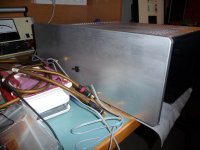
front slab:
I wanted to buy a case but could not find one with right dimensions to accomudate two monoblocks together without being too big. I ended building the case from aluminium pieces I bought in a metal shop. the front slab is 11mm thick in order to carry the two toroidal transformers. each central screw is held in place by an alunimium disk bolted to the front slab. A friend of mine has an old milling machine so I could bring the slabs (front and sides) to the required dimensions. since the front is so thick I had to remove some material to sink the power switch in and allow the neck to pop out on the front. the heat sinks came from a junk shop. it cost about $22 for 4 pieces and is in relatively good cosmetical shape. only the front and heat sinks together weight over 7 Kg. the floor is 4 mm thick to allow for structural support and facilitate threading of all mounting holes. almost everything is screwed directly to it.
overview:
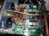
in the overview image, besides the parts you all recognize, one can find (1) common ground (copper slab) which is also a mechanical support for the capacitors and ground disconnect network (attached below). (2) PS for the input buffer mounted on a heatsink taken from a broken PC PS. this is a TeddyReg from PinkFishMedia fitted with trimmers to allow for voltage setting. I'm glad I fitted them in since it allowed me to tune 18V for the DRV and 15V for the OPAs without taking the PS out and replacing resistors. (3) soft start and DC protector. this is a nice device, bought from a very nice guy on DIYAudio (Murray the aussie). it is PIC controled. one can see the power resistor bolted to the floor below the mess of wires between the transformers and the loudspeakers relays (in red) on the back panel on the right. also attached to the back are the input buffers (4).
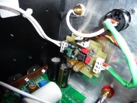
input buffer:
on the left one can see the LM3886TFs held in place by a copper bar screwed to the heat sink with thremal paste to enhance heat transfer. in the center is the input buffer implemented on a strip board 6x5 cm is size. one can see the patch over patch - the SO to DIP adapter and the tiny heatsink (which gets pretty hot) on the OPA1632. if someone is willing to produce a full SMD board with the OPA1632 in thermal package soldered in place and holes in the right position (I can't stand the thought of drilling more holes!) I'm in for 4 borads.
Andrew, I cannot really measure noise. the only measuring device I have is an old scope. I can see it is a high frequency noise from the sweep scale and assess its amplitude when measuring in 2mV/Div to be about 2-4mV peak to peak. however this is no longer relevant for me since I no longer use the DRV and the current input buffer exhibits only a very subtle 100Hz noise I hope to somehow remove. I encounter this kind of noise every time I try to implement something on a strip board. I don't know what it is.
being a coward, I did not connect the amps to my main speakers yet. I attached some junk Sherwood speakers salvadged from a dead mini system. these speaker don't know what hit them. they rock (with the understood limitations, yes?!) like real speakers.
Attachments
Last edited:
neither can I.Andrew, I cannot really measure noise.
But my DMM set to 200mVac or 200mVdc tell me a lot about what is coming out of each amplifier.
If it reads 0.0mVac then the hum and low frequency noise is low.
If it reads 1.0mVac then the noise is bad!
Similarly if it reads 5mVdc the offset is good.
If it reads 20mVdc then the offset is bad.
Pic 1 post 1047 shows a plate across the smoothing caps.
That plate has two sets of red/orange. These must be the centre taps of the transformers.
The plate also has two black and two white wires attached to it.
These will all be at different DC voltage and different AC voltage from each other.
What are you tying into these wires?
Last edited:
neither can I.
Pic 1 post 1047 shows a plate across the smoothing caps.
That plate has two sets of red/orange. These must be the centre taps of the transformers.
The plate also has two black and two white wires attached to it.
These will all be at different DC voltage and different AC voltage from each other.
What are you tying into these wires?
the red/orange are indeed the center taps. the black is the 0V for the PS of the input buffer. the white is the 0V for the PA150s. this arrangement is duplicated per channel. having a single instance of DC protection, I MUST have 0V to be one over the entire amplifier.
the two transformers share only this point and otherwise float so I don't expect to have any voltage drop along the long side of the copper slab. can you see a reason for such drop to develop, i.e. a reason for the transformers' secondaries to be fixed by other potential, different for each?
regarding the short side, there is indeed current flow since the capacitors charge, and it is not symmetric between positive and negative rails. however, I used heavy gauge copper in hope its conductivity will dwarfs any currents flow in it. in practice I cannot measure any (neither longitudal nor transversal) voltage drop but I have a cheapo DMM (about time to upgrade).
If you find my logic above flawed, please explain. I learn from each comment.
for noise, besides the scope, I use the ear inverse distance test. the closer I have to put my ear to the loudspeaker in order to hear noise (given I can tell if it is hiss or hum) the lower I grade the noise (and of course better the situation). this cannot be done of coarse for the input buffer. there I rely on the scope and simply assess the width of the noise band I see on the screen.
the four attachment points are separated. This will develop different voltages, both DC and AC, at the four different points. Guaranteed.I MUST have 0V to be one over the entire amplifier............
........ I don't expect to have any voltage drop along the long side of the copper slab. can you see a reason for such drop to develop,
Do not locate your zero volt reference on or in the smoothing capacitor bridge/link. Never.
From what I can see you are having two separate transformers so you can form two mono blocks. Try to do the wiring as two separate amps in one case. The balance to unbalance to balanced circuits may be fed from a separate power supply if you can't manage the ground loops. Pay also attention to short wires, especially the ground wires. Wires have 1 nH per mm and this can be devastating if you have fast circuits.
Did you get any?Any news on my payed bpa300 boards?
please give me an answer Rhysh.
From what I can see you are having two separate transformers so you can form two mono blocks. Try to do the wiring as two separate amps in one case. The balance to unbalance to balanced circuits may be fed from a separate power supply if you can't manage the ground loops. Pay also attention to short wires, especially the ground wires. Wires have 1 nH per mm and this can be devastating if you have fast circuits.
this was my intention from the start. I had to compromise since I have (and will have) only one DC protection device. I could decouple it from the amplifier (optocoupler?) but I'm not there yet. I agree with your observation on wires. it needs more structural thinking. as for the input section, a separate transformer is possible (if I manage to squeeze something into the already crowded chassis). hopefully I'll manage without. BTW, I prefer to think of it as balanced to balance that can be used as unbalanced to balanced. after all, there is no point in the circuit where to two phases are united.
the four attachment points are separated. This will develop different voltages, both DC and AC, at the four different points. Guaranteed.
Do not locate your zero volt reference on or in the smoothing capacitor bridge/link. Never.
Andrew, in what scenarios you think I will have the largest voltage difference and how do you suggest I measure it? Also, please explain more about the problem arises from my zero voltage.
currently, I don't like the sound of the amplifier. it is not as detailed as I hoped and does not meet my standard (very old but strong tube amp). I entered this project after building a single LM per channel amplifier with a (single) regulated power supply that really surprised me with its clarity and kick on my sensitive mid high part of my speakers. I'm trying to get to someone to help me with measurements to pinpoint the problem.
again, I'm open to all advices regarding what measurement are to be made. I have no experience with such debugging.
 As I said: Think double mono block.
- Status
- This old topic is closed. If you want to reopen this topic, contact a moderator using the "Report Post" button.
- Home
- Group Buys
- BPA300 Round 2