
ygg-it
Regarding the thread changes you asked for... as the changes would involve removing material that has already been built on and replied to it is felt that it would be inappropriate to make the edits. If the material contains errors or requires clarifying then you should simply post new material as 'ongoing' to take the thread forward.
Sorry for posting this here but we are unable to pm you as your profile has the dreaded - which the forum software fails to recognise (it redirects to someone else)
http://www.diyaudio.com/forums/forum-problems/283022-profile-page-redirects-other-user.html
DIY: Add EL34 & KT88 Bias Switch
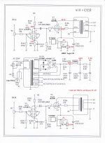
Attached My final modified circuit A10+CCS.
With Toggle SW and 2 color LED lamp.
(EL34 is lit Green, KT88 is lit Red.)
Attached My final modified circuit A10+CCS.
With Toggle SW and 2 color LED lamp.
(EL34 is lit Green, KT88 is lit Red.)
Attachments
ACKBI LEE,
That looks very nice. It should sound good.
Just a few possible changes you might consider:
Remove R101 and R201, and replace with individual 1k Ohm grid stopper resistors at grids pin 2 and pin 7 (4 each 1k for stereo). The gain of the 12AX7 is very high, so there is lots of miller capacitance for the 10k resistors R101 and R201, too much high frequency roll off (unless you want that, -1 dB @ about 26kHz. The output transformer might add another -1 dB rolloff, so -2 dB at 26kHz.
Use individual self bias resistors; 4k Ohms at cathodes pin 3 and pin 8. The 2 sections of the 12AX7 will be certain to very closely share the current that way. And 4 200uF bypass capacitors, use 10V electrolytic.
C102 and 202, R105 and 205 have very long time constants. If the volume is turned too high, or the music has a very large transient such that there is grid current on the EL34/KT88, it will take a very long time for the circuit to 'recover' to normal operation.
The -3 dB point of that RC is 0.6 Hz, much lower than necessary. A 0.22 would give good low frequency response, but would 'recover' 5 times faster.
Hi 6A3sUMMER .
I thank for your advice.
A voltage amplification circuit (parallel triode connection) was slightly strange, but the suggestion thinks me to be a good method.
I intend to try it immediately.
As for the sound quality, EL34 is the Excellent in my impression, and KT88 is good.
Is KT88 current lack?
The primary plan is Ik=100mA (Normal), circuit is 82mA(Cold).
Thanks and Regards.
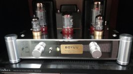
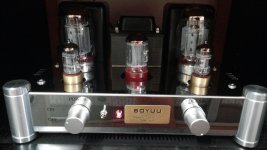
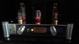
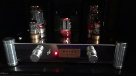
Hi - I've been running my Boyuu A10 for about 1 year now. I have tried EL34, EL34B, 6CA7 and now I ordered a pair of 6P3P to see how they perform. No problems whatsoever, and no need to re-bias. I've not detected any particular performance or sound differences with the valve (tube) variants so far but at least it means I have some spares ")
By using CCS as cathode loading, what's the point till using such great value (470u) of cathode capacitor, that's mean leading tonal balance towards treble ? The CCS just act like a universal tube fix current bias device? Also a large value of capacitor change a CCS into a CVS.
zlab,
The current source establishes the Quiescent cathode current through the output tube (no signal). That and the B+ voltage sets the operating conditions of the output tube.
The 470uF capacitor that is in parallel with that current source, keeps the voltage at the cathode fairly constant as the changing signal dictates different currents through the output tube.
The current source impedance is very high, so those current changes without a capacitor would cause the cathode voltage to vary wildly. You would get less output power, low damping factor, and low gain.
The capacitor has to bypass the varying current caused by signal. The capacitive reactance of the 470uf cap has to be much lower than the cathode impedance (impedance "looking into" the cathode).
If the cathode impedance is 10 times the capacitive reactance at 20 Hz, then the frequency response will be -1 dB versus mid frequency (just due to this one factor; does not include the other parts and circuit parameters; i.e output transformer, RC coupling from driver to output tube, driver tube cathode bypass capacitor.).
Xc, capacitive reactance of 470 uF = 16.9 Ohms.
An EL 84 has about 11,000 micro mhos (cathode Z = 91 Ohms). There is another factor that raises the cathode impedance. It is RL/u. The EL84 screen grid u = 19. This will be affected according to whether you use Ultra-Linear or Triode Wired connections. But for an example, suppose the primary = 3,500 Ohms. 3,500/19 = 184 Ohms. Cathode impedance = 91 + 184 = 275 Ohms. 470 uF is 16.9 Ohms at 20 Hz. We will be less than -1 dB from the factor of the bypass capacitor.
zlab,
At no signal condition: A constant current at the cathode will give a constant current in the plate if either B+ voltage varies, or the tube ages.
At no signal condition: A constant voltage at the cathode will give a different current in the plate if either B+ voltage varies, or the tube ages.
The same is true for Fixed Grid Bias plus a grounded cathode.
See the difference?
100% will lead to short power tube service life.  There are 3 systems for tube ratings: design center (the most conservative), design maximum, and absolute maximum. It is OK to use 100% of design center. Design maximum requires you back off a little. Absolute maximum requires you back off quite a bit.
Some folks claim that tubes sound "better", when run all out. Abused tubes fail and when they fail they don't sound, period.
There are 3 systems for tube ratings: design center (the most conservative), design maximum, and absolute maximum. It is OK to use 100% of design center. Design maximum requires you back off a little. Absolute maximum requires you back off quite a bit.Some folks claim that tubes sound "better", when run all out. Abused tubes fail and when they fail they don't sound, period.
When playing with tube, I think most people concern is neither electric power or money, according specification state that KT66 last 8,000 hours when operate at its rated power. For 10 hours /day, it last for 800 days. If you got a couple pairs for backup, it will be sufficient before your human life end.
If I want to try NFB, would anyone kind enough to give some example?
Yesterday I swap the 12ax7 with we420a silver top. I also re-bias it as per my friend suggestion. Now the anode resistance is 86k & cathode resistance is 1k . The tonal change was excellent.
If I want to try NFB, would anyone kind enough to give some example?
Yesterday I swap the 12ax7 with we420a silver top. I also re-bias it as per my friend suggestion. Now the anode resistance is 86k & cathode resistance is 1k . The tonal change was excellent.
ACKBI LEE, You have very well changed the scheme A10. You have made changes that you advised dear 6A3sUMMER Post https://www.diyaudio.com/forums/tub...-5z4p-rectifier-review-mod-5.html#post5127804 Please indicate on the amplifier circuit the voltage at the control points that you have after improving the amplifier circuit. I strongly dislike the thermal mode of a power transformer Boyuu A10 , The first thing you need to start modifying the A10 with the replacement of a power transformer is a good option. 300W Power Transformer 6550,300B Stabilized filament 2A3,KT88 Tube Buffer | eBay Dear Friends, if anyone has good ideas for improving the performance of the amplifier Boyuu A10, Please share details.Attached My final modified circuit A10+CCS. With Toggle SW and 2 color LED lamp. (EL34 is lit Green, KT88 is lit Red.)
Hi, the most musical is the Russian lamp 6n2p-ev (6н2п-ев), everything else is a compromise.i only have 12at7 in my stock
6Н2П-ЕВ and 6Н2П - lamps are completely different ..... both by sound and by design ... silver is sprayed on the anode of the EB and a grid of gold on palladium supports .... and a simple 6Н2П is consumer goods .
Longroad, thank you for your suggestion to give the best. I will try to run to 6n2p-ev and get something beautiful there, even though it takes time to hunt. is 6n2j equal to 6n2p ?. no I found a manual reference 6n2j, there is only 6n2. for 12at7 I am still curious, have I really right done the method of calculating resistor values?. sorry I just learned and tube is something new to me. and here makes me know a lot.
Last edited:
- Home
- Amplifiers
- Tubes / Valves
- Boyuu hifi Equis A10 EL34B+6N2 SE Tube Amplifier with 5Z4P rectifier: review and mod