Pictures.
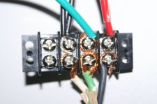
I have included some pictures here. I know the wires in the connector strip don't look nice, but this was made just for testing purposes, the finished amp will have them nicely attached.
I have included some pictures here. I know the wires in the connector strip don't look nice, but this was made just for testing purposes, the finished amp will have them nicely attached.
Attachments
Tell me, do you have one PSU?
How many wire connections is it expecting from the transformer?
Yes, only one PSU for two amp PSBs.
")
Because power = voltage x current. A 4 Ohm speaker needs less voltage but more current to get the same power.Could anybody explain to me why one needs a tranformer with lower secondaries for 4 ohm speakers then with 8 ohm speakers?
An ideal amp that delivers 60 W into a 4 Ohm speaker will only deliver 30 W into 8 Ohm. On the other hand, if you optimise the amp to deliver 60 W into 8 Ohm and connect a 4 Ohm speaker to it, then the amp will try to deliver 120 W and may switch off due to internal protecion circuits or be damaged in the process.
It would be OK for 8 Ohm speakers. With 4 Ohm speakers it would mean pushing it a bit, and it depends on your listening habits, heatsinking and complexity of the speaker load whether it will work in the long run or not.I`m building the same amp also with the XY lm3886 ebay kit. I have a dual 24V tranformer lying around. Would this be OK for both 4 and 8 ohm speakers or just 8 ohm speakers?
Finished Boards.
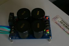
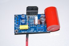
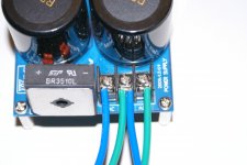
By the way, I just finished the amp boards, I ended up using a Elna Silmic II 47uf 50V in C4, and the Audiophiler MKP 4.7uf 400V in C5.
I soldered the speaker output wire to the bottom part of the copper that comes from pin #3 and includes the Zobel network, I just need to add the Thiele part to that wire, I just don't know how...
Well, here are the pictures, the black stuff in the bottom is liquid electric tape.
Attachments
You can use one of the 15 V windings and add a voltage regulator to it to bring the 21+ VDC you get after rectification down to 12 VDC. It is recommendable to use a resistor in series so that the regulator need not dissipate 9 V times the protection board current.How do I connect the power from the transformer to the speaker protection board?
If you measure 28 V from blue to green, then one blue wire goes to AC, the green one that belongs to it and the other blue wire go to GND and the green that is left over goes to the other AC.On the secondaries side I have 4 pairs of wires, blue and green, blue and green are each 28 volts, then brown and brown, orange and orange are the two secondaries that produce 15 volts each.

Because power = voltage x current. A 4 Ohm speaker needs less voltage but more current to get the same power.
An ideal amp that delivers 60 W into a 4 Ohm speaker will only deliver 30 W into 8 Ohm. On the other hand, if you optimise the amp to deliver 60 W into 8 Ohm and connect a 4 Ohm speaker to it, then the amp will try to deliver 120 W and may switch off due to internal protecion circuits or be damaged in the process.
It would be OK for 8 Ohm speakers. With 4 Ohm speakers it would mean pushing it a bit, and it depends on your listening habits, heatsinking and complexity of the speaker load whether it will work in the long run or not.
Thanks. Would it be possible to use a 4 ohm power resistor in series with a 4 ohm speaker to achieve 8 ohm or would this do good to the sound?
Hey, Fabricated, CONGRATULATIONS AND THE BEST OF LUCK for you and your wife!!!! I know how that feels, I have a 9 months old girl myself...!
This little project has been driving me crazy, but I can't deny I am enjoying it to the fullest, and yes, I would have never embarked in anything like this on my own, these guys here have been of great help, and it is very generous on their part to share the way they do, one of the priceless things in life, knowledge. I am still struggling with schematics, I tried to recreate one with my PCB boards and after 5 hours I gave up, but I'll get there...
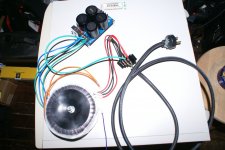
Now I am almost ready to test what I have done, I am going to get all this stuff hooked up on the top of that old desktop computer you see on the pictures I just posted, I just want to hear this thing playing some Jethro Tull, just one input for now, after I do that, I'll get the enclosure and add the input selector board and the rest of the stuff.
So far I believe that your thread and mine are the best ones regarding the "LM3886 chip for dummies", specially for those buying the XY boards at eBay, I think that these guys, specially AndrewT, should "copyright" both threads (including his clever Zobel + Thiele implementation for these boards), I'm sure the chinese sellers at eBay will be including a link to these threads in the package for the buyers.
This little project has been driving me crazy, but I can't deny I am enjoying it to the fullest, and yes, I would have never embarked in anything like this on my own, these guys here have been of great help, and it is very generous on their part to share the way they do, one of the priceless things in life, knowledge. I am still struggling with schematics, I tried to recreate one with my PCB boards and after 5 hours I gave up, but I'll get there...
Now I am almost ready to test what I have done, I am going to get all this stuff hooked up on the top of that old desktop computer you see on the pictures I just posted, I just want to hear this thing playing some Jethro Tull, just one input for now, after I do that, I'll get the enclosure and add the input selector board and the rest of the stuff.
So far I believe that your thread and mine are the best ones regarding the "LM3886 chip for dummies", specially for those buying the XY boards at eBay, I think that these guys, specially AndrewT, should "copyright" both threads (including his clever Zobel + Thiele implementation for these boards), I'm sure the chinese sellers at eBay will be including a link to these threads in the package for the buyers.
AndrewT and Pacificblue, you guys are the BEST!!! Thank you!!!!
AndrewT and Pacificblue, you guys are the BEST!!! Thank you!!!!
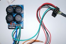
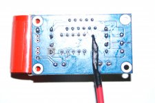
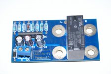
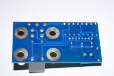
Here is a picture of the "speaker protection board" I have. It only has a connector block with GND and 12V as you can see in the picture. I was expecting AC GND AC and this is very confussing for me, does this mean it has to be powered by DC????
Also, do I just solder the + LEFT and + RIGHT outputs coming from the amp PCB's to the holes in the other end of the board, and then simply attach the speaker output connectors to the board?. I am including pictures of top and bottom.
Thank you again...!
AndrewT and Pacificblue, you guys are the BEST!!! Thank you!!!!
Here is a picture of the "speaker protection board" I have. It only has a connector block with GND and 12V as you can see in the picture. I was expecting AC GND AC and this is very confussing for me, does this mean it has to be powered by DC????
Also, do I just solder the + LEFT and + RIGHT outputs coming from the amp PCB's to the holes in the other end of the board, and then simply attach the speaker output connectors to the board?. I am including pictures of top and bottom.
Thank you again...!
Attachments
If you measure 28 V from blue to green, then one blue wire goes to AC, the green one that belongs to it and the other blue wire go to GND and the green that is left over goes to the other AC.
So that would be (2 x 28) x 1.4 = 78.4 Vdc. Meaning that when both amp boards are connected in parallel each amp would recieve 78.4 Vdc from positive to negative and 78.4 / 2 = 39.2 Vdc from positive to ground and -39.2 Vdc from negative to ground. Right?
Pacificblue:
Thank you for that image regarding the right way to connect the toroidal to the power supply. I am going upstairs right now to fix it, I had connected BLUE with BLUE and GREEN with GREEN together, and a GRD that goes to the mains GRD in the middle, now I see the right way to do it, thanks again.
Thank you for that image regarding the right way to connect the toroidal to the power supply. I am going upstairs right now to fix it, I had connected BLUE with BLUE and GREEN with GREEN together, and a GRD that goes to the mains GRD in the middle, now I see the right way to do it, thanks again.
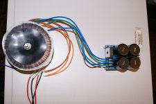
Right way to connect secondaries to PSU.
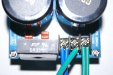
Ok, for the rest of the dummies out there (I'm pretty sure I'm not the only one) here is the pictures showing the correct way of connecting the two secondaries to one PSU board, thanks to Pacificblue. The screw on the left of the PSU reads AC, the middle GND and the one on the right AC.
Now when I measure the other end of the PSU (DC coming out side), where the terminal connector block shows +V GND -V, when measuring from +V to -V I get a reading of 80 volts, and when reading from any of the V's to GND I get 40 volts.
Attachments
So that would be (2 x 28) x 1.4 = 78.4 Vdc. Meaning that when both amp boards are connected in parallel each amp would recieve 78.4 Vdc from positive to negative and 78.4 / 2 = 39.2 Vdc from positive to ground and -39.2 Vdc from negative to ground. Right?
That is correct, I just measured mine, I get 80 volts from +V to -V, and 40 volts from any of the V's to GND.
Pacificblue, my toroidal has an additional wire because it is a "shielded toroidal", that wire is purple in color, what do I do with it?.
Connect it to the safety/earth ground.
Pacificblue, my toroidal has an additional wire because it is a "shielded toroidal", that wire is purple in color, what do I do with it?.
The shield connects to ground.
Is this a Zobel?
Hi Andrew. I've been reading this post with attention because I built the same kit about a year ago, and since then I´ve enjoyed it very much, with no problems at all.
Now I read that there is something missing in the circuit: "a Zobel network". Is this what you are talking about?
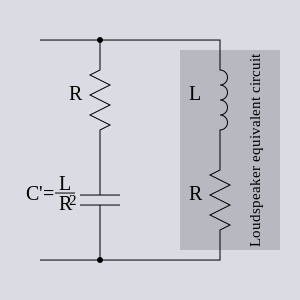
What are the values of the cap and resistor that you recommend? (I don't understand this 2r0)
Thanks and RGDS
Pemo
There is no provision for an output Zobel.
Use the locations of R1 and the speaker terminal to fit an R+C Zobel.
R1=2r0 to 10r
Speaker terminal=47nF to 220nF.
Add the other half of the Thiele Output Network, the R//L, off the PCB. R=2r0 to 10r L=0.5uH to 1.5uH
Insert a thick copper wire in this pad first, The top end of R1, nearest the output PIN.
Attach R1 to the copper wire.
Take the speaker output from the top end of R1. Attach the speaker wire to the copper wire. I suggest you fit the speaker wire on the bottom side.
You could bend over the top side of the copper wire to lie on top of the output PIN. Solder this connection. But fit a temporary tab heatsink next to the package since quite a bit of heat will try to travel along this PIN during soldering.
Hi Andrew. I've been reading this post with attention because I built the same kit about a year ago, and since then I´ve enjoyed it very much, with no problems at all.
Now I read that there is something missing in the circuit: "a Zobel network". Is this what you are talking about?
_Zobel_loudspeaker_impedance_correction.svg)
What are the values of the cap and resistor that you recommend? (I don't understand this 2r0)
Thanks and RGDS
Pemo
- Home
- Amplifiers
- Chip Amps
- Bought a XY LM3886 Kit.