Thanks for the info Grataku! I think i'll try and do a
C-R-C to drop the voltage like you did.
What value would the R be? Would you use something
like a 3W or 5W resistor at x Ohms?
I'm just waiting for replacement parts to give it another go.
Originally i think i may have caued a short with the probes
while tring to get the first readings, or i had a part misplacement.
Live and learn right?
thanks again,
m.
Moe, if that's what you want to do you should calculate the R out. I don't remember what is the current draw/chn on the bosoz, I closed up mine last night so I don't feel like re-open it to look. Use ohm's law to calculate R and the dissipated power for a ~25 V drop. I remember using some serious resisitors for that like a 15 watt or so.
enamel
Moe, cheer up mate i found this @ digikey
after talking to paolo I invested in a pair of these
vitreous enamel wire wound resistor, the adjustable version 50 w
http://dkc3.digikey.com/PDF/T031/0719.pdf
Moe, cheer up mate i found this @ digikey
after talking to paolo I invested in a pair of these
vitreous enamel wire wound resistor, the adjustable version 50 w
http://dkc3.digikey.com/PDF/T031/0719.pdf
moe29
This could be another solution.
Assuming all components are soldered in the right places, I think that the rectified plus and minus 104V are just applicable to the existing regulator system if two things are provided. First, I recommend that the rated voltage of the filter capacitors is to be 135V. Second, I recommend that Q101 and Q102 are to be put on bigger heat sinks. As you know very well, we need the rail voltages of plus minus 60V to the amp circuit. This mean that the remaining plus and minus 44V are to be cut off by the Q101 and Q102, and it will generate the increased heat. Since the original Nelson Pass article informs that the current flow to each channel is about 80mA, total about 160mA current will flow through Q101 and the same through Q102. Therefore, each of Q101 and Q102 will generate heat power of about 44 x .16 = 7W. I would arrange a good size of each heat sink taking care of about 10W heat. Hoping this info will help.
JH
Moe,
Ohm's law for future reference (it really works as advertised!): R=V/I=25/0.16~160 ohms. The rating: P=V^2/R or R*I^2~4 W (round off to 10W rating).
The only reason I did a CRC was because having a 20 W heatsink over the PS board was not possible for me, plus I couldn't find a correctly rated cap that would fit in the same footprint on the board. I actually used the standard ps board myself: I went from the rectifier on board to a pair of outboard caps and a couple of Rs then back to the onboard 1000/100 VDC caps/ regulator. This was done p2p from the board.
You will find that a 10W heatsink (or 2 10 W) is rather large.
I remember being unable to find an HS profile that would fit on the board and be nicely secured to it without doing some custom machining to it
Hey Grataku,
After browsing Digikey i see what you mean. The capacitor
i found has a 30mm diameter, the stock cap is 25mm... there isn't
enough room for it on the stock board! And the heat sinks i found
on Digikey are pretty big too. 294-1027-ND / 294-1068-ND.
so, it's either modify the stock board to fit these parts, which
would mean etching another board, or try to implement the
offboard parts like you did. (or get better transformers!)
Did you have to cut the traces between the bridge and the
capacitor?
When you mentioned Ohm's Law i got out my trusty "Getting
Started in Electronics" by Forrest M. Mims, III! I had come to a
160 ohm resistor too, but not the way you did. I figured i knew
the target Voltage - 80V and i knew the Current - 0.5 amp, the
draw of the transformer. So 80/0.5=160. But i had no idea if
that was a correct starting point.
m.
moe29 said:I had come to a
160 ohm resistor too, but not the way you did. I figured i knew
the target Voltage - 80V and i knew the Current - 0.5 amp, the
draw of the transformer. So 80/0.5=160. But i had no idea if
that was a correct starting point.
I'm afraid that you were just lucky, moe, because that's not the right calculation. The voltage drop is across the resistor that you are planning to add (that's what you're putting it there for). How much is that? Say, about 25V (104-80). And the current that flows through that resistor? As jh6you and Grataku both said, it's .16A. The construction article mentions that each channel draws half that amount from the supply. So, V=IR, and R=V/I where V is 25 and I is .16. You get 156; call it 160. Pretty smart cookie that Grataku. Ohm's law you'll use more than anything else in this business.

Still Having Problems
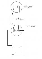
On the unmodified PCB i was getting a reading of 102V on
the first cap after the bridge. Trying to get this reading down to
80V i implemented this C-R-C.
i'm still getting a 102V reading off of the 100V 1,000uF capacitor.
evidently i did not do something right. In despiration i put another
160 ohm resistor between the negative poles of the caps... still
the same reading. So what am i doing wrong?
any help would be great
thanks
m.
that would seem to make sense, but the wiring was done
point to point. The resistor is in the circuit, but seems to have
no effect, since the 2nd cap is getting the same reading.
both capacitors seem to be viable, as they hold a charge after
power is turned off.
I guess my next step will be to etch a new board (based on the
circuit art in the BOSOZ article) with room for the 200V 1,000uF
capacitor (C101 & C102) and larger heat sinks for the Q's. Since
I can't seem to negotiate a voltage drop to run the rest of the
parts in spec.
I guess I know what Transformers i'm NOT going to buy next time.
It's a shame because i have the same make allready purchased
for the SOZ...
m.
moe29 said:
... larger heat sinks for the Q's.
Hope this info will help.
Presuming no sound quality degradation, I would reduce the bias current from the original 40mA to 20mA. Then, total current flow would be 80mA through Q101 and the same through Q102. This results in reduced heat dissipation of 0.08 x 45 = about 3.6W to each heat sink. To do this, I would scale up R1, R2, R3, R4, R5, R6 and R15 by the factor of 2.
JH
Another Power Supply for your Viewing
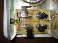
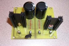
Moe29,
Just want to let you know that i've finished helping my friend build the power supply of this preamp.
I've built this power supply many times and will say this one is the best i've done so far. We used the same PCB design that I drew out on my computer and had a local shop make the boards for me. Design factors I considered was to allow the mosfets to be mounted vertically so you can accomodate larger size heatsinks. Also I tend to like smaller, compact layouts.
What really impressed me was the accuracy of voltage we got. After spending hours matching zener diodes and mosfets, I could not believe the output rail voltages were DEAD ON the same. Normally I would be at least a 1/2 volt out but this time it was like +57.4 & -57.4 VDC.
We used a single 300VA 50 + 50VAC toroidal transformer and ran each 2ndary to each bridge. For the caps we used 1200uF.
The regulation of the voltage is quite important. It would not matter if we used a 60 + 60 VAC transformer because the regulated output VDC would still be at 57.4V. The only drawback is more heat dissipation on the mosfets which is why the 50 + 50 donut had fit the job nicely (and the bill also). We confirmed this by use of my Varaic, as 57.4V would be reached at 200volts and as we increased the voltage to 240VAC, the voltage rail remained stable.
As for blowing up the diodes, I did NOT seem to have any problems powering up this board with no load on the output rails. Perhaps the abnormal super high voltages you measure were the cause of the zeners blowing up? I do know that the heatsinks do not heatup unless there's a load being drawn from the rails. So testing the board out on a bench with no load shouldn't present any problems. Triple check all connections - maybe you have the 2ndaries wired in series where the voltage will double up after rectification.
BQ
Attachments
it works!!
just wanted to post and say that i finally got the power
supply working!
I'm a geek to be happy about a PSU working, but hey,
it's a start")
thanks for everyone's help, just be ready when i ask more
stupid questions getting the main board working!
<Mr Garrison>Remember class there are no stupid questions,
just stupid people!</Mr Garrison voice>
m.
just wanted to post and say that i finally got the power
supply working!
I'm a geek to be happy about a PSU working, but hey,
it's a start
thanks for everyone's help, just be ready when i ask more
stupid questions getting the main board working!
<Mr Garrison>Remember class there are no stupid questions,
just stupid people!</Mr Garrison voice>
m.
Attachments
Update - DO NOT SNEEZE!!! : Help on source voltage cutting out
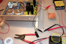
Just an update, trouble shooting the BLS on my friend's project. While I was testing for voltages on the mainboard, my friend accidentally SNEEZED and some of the over spray landed on the power supply board.
A flash of smoke, crackle and POOF! something went wrong. I continued to check the voltages on the power supply and the V+ and V- was out by some volts. Actually, i've narrowed it down to the 1st zener in the stack that was taken out by my friend's fatal sneeze.
On the trouble shooting the mainboard, anyone have an idea where to look - one IRF610 mosfet tends to cut out at higher voltage (around 50 vdc rail)? The -4 (source) reading is stable for the other channel but for this mosfet, at lower voltages I get a normal reading around -3.8 volts or less. WHEN I increase the voltage on my Variac, and as the 'source' voltage increases from say -3.8 to like -3.92... it CUTS out and drops back to like a measling low minus voltage. Not to mention the gate and drain voltages go way higher and unmatched with the other transistor.
BTW, we've replaced the mosfet and same problem occurs.
BQ
- Status
- This old topic is closed. If you want to reopen this topic, contact a moderator using the "Report Post" button.
- Home
- Amplifiers
- Pass Labs
- BOSOZ Psu