Ok, I have an update of sorts.
When I power up the amp through my DBT using a 100 watt bulb (and using shorting plugs on the outputs), the power on/off relay starts buzzing. So I just shut off the amp. Not sure how to interpret that, and I'm loathe to see what would happen without the DBT before first getting your thoughts.
When I power up the amp through my DBT using a 100 watt bulb (and using shorting plugs on the outputs), the power on/off relay starts buzzing. So I just shut off the amp. Not sure how to interpret that, and I'm loathe to see what would happen without the DBT before first getting your thoughts.
OK ")
I can't just spot a power relay on the circuit and so don't know how its operated. The DBT should protect against most overcurrent situations and so I'm inclined to say temporarily short out the power relay so that it can not interrupt the supply. It may be doing what it does simply because the supply voltage is low because of the bulb.
You should also set the bias to minimum on both channels for initial testing.
You are going to have to be sure in your own mind about this because it could be configured in different ways, for example switching L and N or perhaps just L. If the later then the contacts may be in parallel, or maybe not.
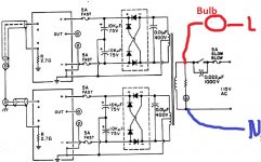
All you need to do is to ensure the AC line voltage is applied across the transformer secondary. Just do a resistance check from L and N on the mains lead and see where they go.
All you need to do is to ensure the AC line voltage is applied across the transformer secondary. Just do a resistance check from L and N on the mains lead and see where they go.
It probably is easier to short the relay.
Link 3 to 5 and 4 to 6 and then check with your meter that you read a low resistance (the transformer primary) but not a dead short. The transformer could read as low as just a few ohms at DC, that's normal. You will have to link the bulb out for the resistance check, then put it back.
In any case with a bulb in place, even if you short the mains out in the amp it wouldn't matter, the bulb would just light.
Those resistances suggest you could be measuring components related to the relay and any soft start circuitry... all an unknown.
Don't sweat the fine print over this all you are interested in is connecting mains across the transformer primary with a bulb in series with it all. I would just short the pins on the relay out (as in my post above) and just try it. Even you placed a dead short across the mains, all that would happen is the bulb would light.
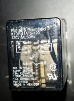
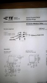
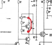
The relay clicks 'closed' when the amp is on normally. So just short the pins that are (with the amp OFF) reading open, and those pins based on the picture and the data sheet are 3 and 5, and 4 and 6.
Don't sweat the fine print over this
all you are interested in is connecting mains across the transformer primary with a bulb in series with it all. I would just short the pins on the relay out (as in my post above) and just try it. Even you placed a dead short across the mains, all that would happen is the bulb would light.The relay clicks 'closed' when the amp is on normally. So just short the pins that are (with the amp OFF) reading open, and those pins based on the picture and the data sheet are 3 and 5, and 4 and 6.
If we have doubts over the relay, what we are shorting and what any other soft start circuitry might be doing then we just go the direct route and disconnect the primary from whatever is in there and apply AC mains (via the bulb of course) straight onto the primary windings.
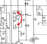
There may not even be a problem at all. The amp might be taking more current than a bulb can supply. So what we do is force a zero bias condition by shorting the bias generator transistor. The DC100 and DC100 Servo show slightly different arrangements with one using an NPN device and the other a PNP. The principle is the same though. Shorting the device removes any gate voltage differential from the driver transistors. The amp should work normally but with no bias current and so slightly higher distortion. You would need to do this on both channels. Shorting the small cap across the transistor is probably the easiest route.
There may not even be a problem at all. The amp might be taking more current than a bulb can supply. So what we do is force a zero bias condition by shorting the bias generator transistor. The DC100 and DC100 Servo show slightly different arrangements with one using an NPN device and the other a PNP. The principle is the same though. Shorting the device removes any gate voltage differential from the driver transistors. The amp should work normally but with no bias current and so slightly higher distortion. You would need to do this on both channels. Shorting the small cap across the transistor is probably the easiest route.
Attachments
Update: With help from Mooly I was able to successfully bypass the relay and test each channel separately with my DBT. They both passed. I also adjusted bias and then lowered it back down again.
I now have the amp powered on without the DBT. The recommended bias setting, when measured across the 0.22 ohm source resistors, is 22mV. I'm giving the amp about 10 minutes or so to warm up before making my final adjustment. Then I'll check DC offset.
I now have the amp powered on without the DBT. The recommended bias setting, when measured across the 0.22 ohm source resistors, is 22mV. I'm giving the amp about 10 minutes or so to warm up before making my final adjustment. Then I'll check DC offset.
100ma per FET is considered optimal from a bias stability point of view as this is where the temperature coefficients cancel out. At higher currents they have a negative tempco, at low currents I believe it is slightly positive. Anyway, 100ma was always the recommended optimum historically.
After what I've gone through trying to get this amp sorted out, I'm not pushing the bias (or my luck)!
Bias adjusted to 22mV and DC offset to ~0mV. I hooked up my sacrificial test speakers and played music at moderate levels for about 45 minutes. Heatsinks became slightly warm. I'll recheck the bias again tomorrow and do some more listening.
Bias adjusted to 22mV and DC offset to ~0mV. I hooked up my sacrificial test speakers and played music at moderate levels for about 45 minutes. Heatsinks became slightly warm. I'll recheck the bias again tomorrow and do some more listening.

- Status
- This old topic is closed. If you want to reopen this topic, contact a moderator using the "Report Post" button.
- Home
- Amplifiers
- Solid State
- Borbely DC 100 Amp: Left Channel Troubleshooting