Hi Francois,
Yes, you got my question just fine. I, just today, decided that I am going to go with the quad of KT88s or 6550s. If not, I'd have a pile of transformers in the floor for a year")
Rationale? Yes, the octet of EL34s might give lower distortion, but it is also twice the circuitry for bias, etc.
I plan to take my time on this one. I have built and tinkered with many amps, and I know that it is a journey and not a destination.
I will receive my screen chokes this week sometime, and then I will drill the holes for them and take a short break while I gather chassis parts and resources. Builds like this get expensive quick!
I will take plenty of images and make sure it is documented. I think there are a bunch of these out there and people trying to decide what to do with them.
Blair
Yes, you got my question just fine. I, just today, decided that I am going to go with the quad of KT88s or 6550s. If not, I'd have a pile of transformers in the floor for a year
Rationale? Yes, the octet of EL34s might give lower distortion, but it is also twice the circuitry for bias, etc.
I plan to take my time on this one. I have built and tinkered with many amps, and I know that it is a journey and not a destination.
I will receive my screen chokes this week sometime, and then I will drill the holes for them and take a short break while I gather chassis parts and resources. Builds like this get expensive quick!
I will take plenty of images and make sure it is documented. I think there are a bunch of these out there and people trying to decide what to do with them.
Blair
Still not quite sure where this is going. It looks like you're basically building new amps from scratch using the MO200 iron. If so, you need to look at the OPT primary impedance vs the operating point of whatever tubes you choose, since they will not be 8417s. I would hash out that design detail first before arbitrarily choosing the output tubes. Otherwise you may find yourself in a bind.
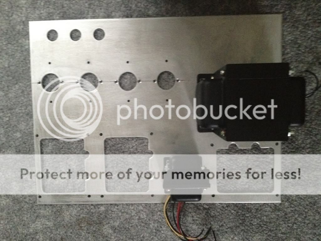
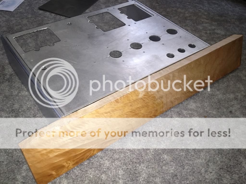
Here is what I did today. I have the other channel cut as well, but no donor amp yet
Blair
Blair,
That top plate looks great! You must have access to a laser cutter. I have been dreaming about chasses like yours.
Is your choke at the right bottom as shown in the picture? If so, provided the laminations are 90 degrees from the power trannie, this looks like a good layout to me. What is the small tranformer mounted in the bottom row? Heaters?
I know the purists would like you to turn the two output transformers (if used in stereo) but the crosstalk has been inaudible to me. if used in MO-200 mode it would make no difference, of course. (I think)
Francois
I have mentioned it several times that the primaries are 4.5K on the output iron. Looking at both the KT88 and 6550 datasheets, they will work well into that load with 300V on the screens. Yes, I'm not building the bogen amp, or I would have just used the original chassis.
Blair
Blair
Hi Francois,
Nah, just a redneck and a drill press I've been building amps for about 10 years. Just not too many that aren't proven designs.
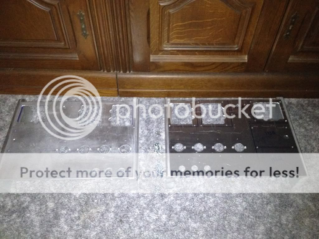
In the image, the bottom row is: OPT, OPT, screen transformer, power transformer.
Just above the power transformer is the 193Q, and not drilled and mounted is a 7H choke for my screens. I plan on using a choke regulated input to drive my screens and driver tubes plates.
Blair
Nah, just a redneck and a drill press
I've been building amps for about 10 years. Just not too many that aren't proven designs. In the image, the bottom row is: OPT, OPT, screen transformer, power transformer.
Just above the power transformer is the 193Q, and not drilled and mounted is a 7H choke for my screens. I plan on using a choke regulated input to drive my screens and driver tubes plates.
Blair
Still not quite sure where this is going. It looks like you're basically building new amps from scratch using the MO200 iron. If so, you need to look at the OPT primary impedance vs the operating point of whatever tubes you choose, since they will not be 8417s. I would hash out that design detail first before arbitrarily choosing the output tubes. Otherwise you may find yourself in a bind.
I do agree, since it is essentially a new amp design, from scratch. That was why I mentioned the different driver requirements - perhaps not explicitly enough.
But I expect our builder Blair was well aware of that.
Francois
Hi Francois,
Nah, just a redneck and a drill press
In the image, the bottom row is: OPT, OPT, screen transformer, power transformer.
Blair
Hi Blair,
That is truely impressive redneck drill press craftmanship! I guess bourbon was another redneck accomplishment, so I should not be surprized. Or was bourbon a Southernly Gentlemen's accomplishment. (Please pardon me if I am treading on sacred ground!)
Again, sorry if I missed previous discussion, but what front-end/phase splitter are you using? As was pointed out that could have more effect or beneficial influence than the 3dB gained in doubling the power by going MO 200 from 100. Unless you have very inefficient speakers 200 vs. 100 watts is probably not an important factor in your ultimate fidelity. FWIW I am planning to have my Bogens as two MO-100's
Best,
Francois
Hi Francois,
I have LOTS of practice drilling chassis!
I am looking at Williamson front ends. I plan to use some CCS on the PI at least, but I'm not sure what I will do yet. It really depends on the layout and how crowded things get.
I am using mine in original parallel form because the output impedances are a bit more practical at 8, 3.125 ohms.
My speakers are large passive dipoles that are about 89-90db.
Yes,
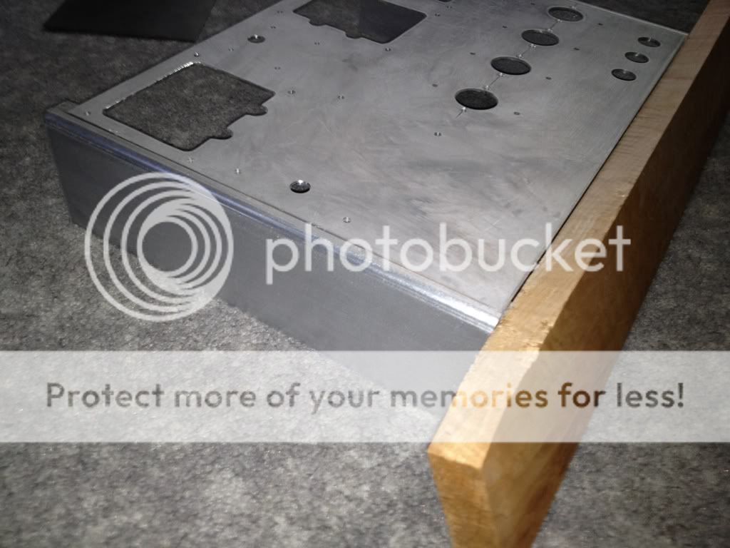
I'm still not sure what I will do for a driver which is why I have the three holes drilled. If you look, it's marked for a potential fourth if needed.
I have to complete the chassis first though.
I have to get the 1" bar stock to mill for the sides.
Blair
Blair,
Have you considered some of the exellent input PC board and designs one could buy for very reasonable prices? Personally I plan to use Kevin Kennedy's octal input PCB for my rebuild. (If interested in my plans let me know)
If you choose to design your own input circuitry and do point to point wiring it probably matters less, but I feel it is important to lay out the parts (especially sockets, large caps and transformers first) before doing the chassis. Since you are experienced perhaps you have a preferred way of doing it.
I do things a bit less practical. I drill things, machine, assemble and then figure out where I will put things it helps when you use solid materials that you can drill in to. The big choke really helps also because there will be less monster caps in series.
I'm not too worried
Blair
it helps when you use solid materials that you can drill in to. The big choke really helps also because there will be less monster caps in series. I'm not too worried
Blair
Blair,
Please keep us informed of your progress. I would especialy like to know what front-end you ended up with and how it worked out for you.
BTW, I would not expect that you really could use ~200 w/ch on you 90 dB/ w speakers, or you have a much more understanding wife than I do.
Francois
Please keep us informed of your progress. I would especialy like to know what front-end you ended up with and how it worked out for you.
BTW, I would not expect that you really could use ~200 w/ch on you 90 dB/ w speakers, or you have a much more understanding wife than I do.
Francois
Hi guys,
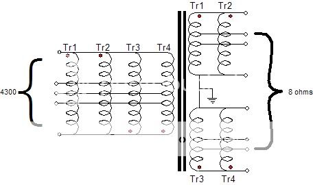
What's the difference and benefits/cons of these configurations?:
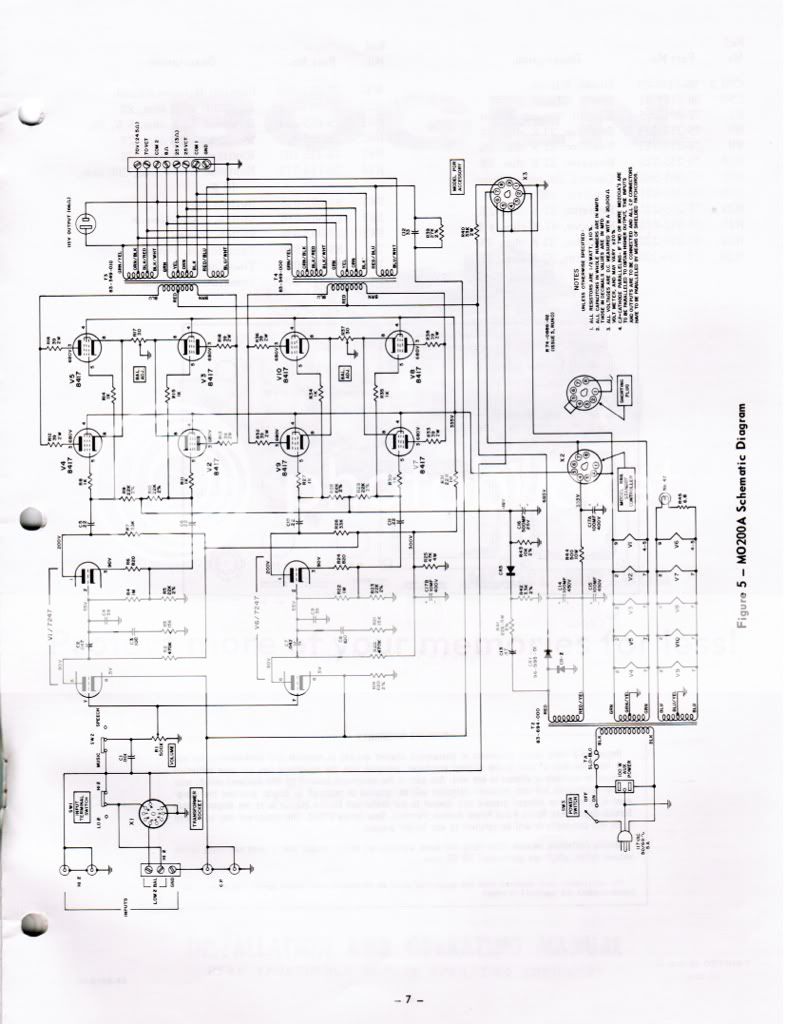
As described here: Big Amplifiers
And this:
The big difference I see is that the primaries are also parallel in the first image.
In the bogen, he parallels the outputs and uses the two 16 ohm taps in parallel to make an 8 ohm tap. Does this keep the primary impedance of each transformer the same as a reflective load as long as you use an 8 ohm load on the two 16 ohm taps in parallel?
I really want to make sure I am going to be dealing with the primary impedance of 4.5 K as tested on each individual transformer after paralelling or "strapping" them.
Thanks!
Blair
What's the difference and benefits/cons of these configurations?:
As described here: Big Amplifiers
And this:
The big difference I see is that the primaries are also parallel in the first image.
In the bogen, he parallels the outputs and uses the two 16 ohm taps in parallel to make an 8 ohm tap. Does this keep the primary impedance of each transformer the same as a reflective load as long as you use an 8 ohm load on the two 16 ohm taps in parallel?
I really want to make sure I am going to be dealing with the primary impedance of 4.5 K as tested on each individual transformer after paralelling or "strapping" them.
Thanks!
Blair

Has anyone ever done anything like the output transformer configurations I posted above? I just wonder if there are any benefits to one over the other. If the primaries are paralleled, then a primary impedance on 2,250k is seen by the tubes, and if done the way Bogen did it with the secondaries paralleled only, the tubes in each "amplifier" will see 4.5k.
Thanks,
Blair
Thanks,
Blair
The "primary impedance" seen by the tubes is dependent on what you connect to the secondaries. The transformer itself doesn't have a specific "primary impedance".
In the original Bogen configuration, I believe each QUAD of tubes sees somewhere around 2.2k if memory serves. When connecting speaker impedance per markings on the back panel (i.e. 8 ohm speaker to 8 ohm output screw). You can calculate various configurations from that.
As far as paralleling the primaries or not, I think that boils down to driving the power tubes. In one case you're driving all the finals from one driver, in the other case you only drive half of them from each driver.
I would be reluctant to have a single 7247 drive 4 pairs of 8417s, but I haven't tried it. Apparently Bogen felt the same way. So you have to look at what output tubes you're using, how many, operating points, etc. then calculate the drive requirements and see what driver tubes, and how many, you need.
Thanks,
I think I have not been explanatory enough in my venture. I'm not trying to replicate Bogen's design at all, but rather build a better front end. Possibly an EF56/6H30 combo.
Anyway, I used a variac to determine the OPT primaries based on the original loads, and they are around 4.5K each, so fully parallel, they would be 2.25k which would be perfect for PPP KT88 or 6550s.
I do like the idea of using a single driver circuit vs. dual drivers.
I have never fully paralleled output iron, so I am a bit concerned about the results.
Thanks,
Blair
- Status
- This old topic is closed. If you want to reopen this topic, contact a moderator using the "Report Post" button.
- Home
- Amplifiers
- Tubes / Valves
- Bogen MO-200A transplant /conversion