scott wurcer said:Yes, I'm still interested to know if anyone has gotten that LTC "no" distortion oscillator to work.
Oscillators to ham radio guys are like 6 cylinder Ford engines. You just can't stop tinkering with them:
You mean this?
An externally hosted image should be here but it was not working when we last tested it.
The fundamental isn't entirely notched out by my Tektronix THD analyzer.
An externally hosted image should be here but it was not working when we last tested it.
Who said that Vishay ,'bulk metal' resistors are best for audio? NOT me. I tend to use Vishay (now) Roederstein that cost me 0.05-0.10 dollars each. They don't have any measurable distortion either, but their tempco is not as good as 'bulk metal'. Cheap shots, even as a joke, are misleading to others, Scott.
scott wurcer said:
Paul Brokaw and Mitch Madique presented cross quaded input devices and outputs on a thermal center line with NO thermal feedback (fractional ppm) more than thirty years ago, it was then end of story.
Yes, but the interesting question is, are these methods sufficient (that seems implied in your answer) and are they standard methods used in (almost) all opamps since long, or used only in som high-performance ones?
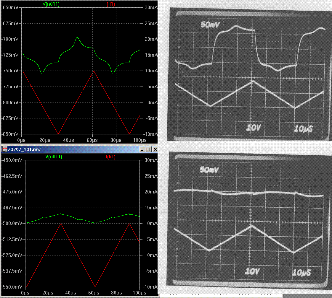
My AD797 simplified circuit sim
http://www.diyaudio.com/forums/showthread.php?postid=1525757#post1525757
modified to match the conditions of Scott's AES paper and compared with his pic (from the previous page of that thread)
some scale differences but remarkable congruence of waveform features temps me to believe the sim can “explain” the bumps at zero (output current) crossing
Av 1000 amp, input to gnd, +/-10 mA triangle ramp pulling on the output (output V =green trace)
top with full 50 pF internal comp limiting high frequency gain
bottom with Scott's “distortion canceling” Cn (increased Vres to see any features)

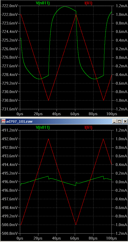
1st we can dismiss John's characterization of this as crossover distortion, simply run the output stage Class A by changing the output current ramp to +/- 1mA which keeps within the push-pull Class A operating range of the 500 uA output Q bias (to me using the term "crossover distortion" unmodified implies a static nonlinearity)
all John has to do is buffer the output to get this level of linearity, keeping the AD797 in its Class A operating range
again the top trace is without Scott's recommended Cn, lower with Cn

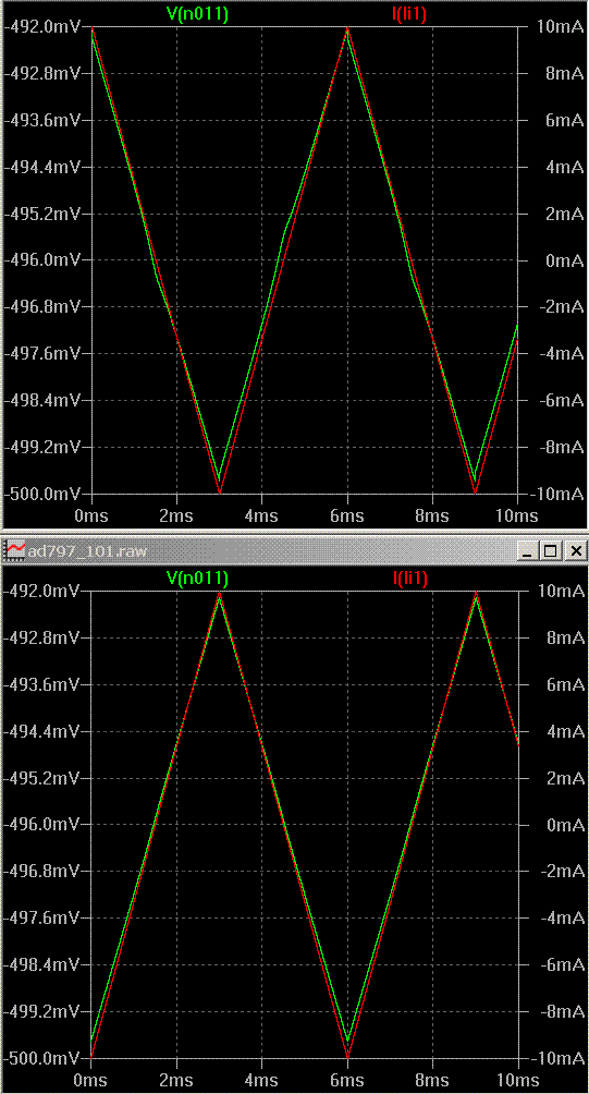
2nd we can see that at 16 Khz Scott's test is pretty fast, so what does the sim show at 100x slower?"
note the V scale is 8 mV full scale, compare to over 100 mVpp error waveform amplitude in the 1 plot without Cn
a little slope change is evident without the Cn cap in the top sim, the bottom looks as linear as could be desired

I think these sims are enough to finger the dynamic charging requirement of full output transistor commutation when running the output devices Class AB as the real “crossover hat” culprit in Scott's AES pics
perhaps external Class A bias would also achive higher high frequency linearity by avoiding the output Q commutation - I would rather use a few more components to make a buffer in the feedback loop after Jung and not have to consider the skewed bias conditions inside the chip and also totally ignore thermal feedback
http://www.diyaudio.com/forums/showthread.php?postid=1525757#post1525757
modified to match the conditions of Scott's AES paper and compared with his pic (from the previous page of that thread)
some scale differences but remarkable congruence of waveform features temps me to believe the sim can “explain” the bumps at zero (output current) crossing
Av 1000 amp, input to gnd, +/-10 mA triangle ramp pulling on the output (output V =green trace)
top with full 50 pF internal comp limiting high frequency gain
bottom with Scott's “distortion canceling” Cn (increased Vres to see any features)

1st we can dismiss John's characterization of this as crossover distortion, simply run the output stage Class A by changing the output current ramp to +/- 1mA which keeps within the push-pull Class A operating range of the 500 uA output Q bias (to me using the term "crossover distortion" unmodified implies a static nonlinearity)
all John has to do is buffer the output to get this level of linearity, keeping the AD797 in its Class A operating range
again the top trace is without Scott's recommended Cn, lower with Cn

2nd we can see that at 16 Khz Scott's test is pretty fast, so what does the sim show at 100x slower?"
note the V scale is 8 mV full scale, compare to over 100 mVpp error waveform amplitude in the 1 plot without Cn
a little slope change is evident without the Cn cap in the top sim, the bottom looks as linear as could be desired

I think these sims are enough to finger the dynamic charging requirement of full output transistor commutation when running the output devices Class AB as the real “crossover hat” culprit in Scott's AES pics
perhaps external Class A bias would also achive higher high frequency linearity by avoiding the output Q commutation - I would rather use a few more components to make a buffer in the feedback loop after Jung and not have to consider the skewed bias conditions inside the chip and also totally ignore thermal feedback
Christer said:
Yes, but the interesting question is, are these methods sufficient (that seems implied in your answer) and are they standard methods used in (almost) all opamps since long, or used only in som high-performance ones?
I don't mean to appear high-handed. The "gull-wing" effect shown in Solomon's paper is eliminated by these methods. There is certainly a shift in bias point with temperature and there might be some subtle second and third order effects. Cross-quading of input devices and thermally centering the output devices is a pretty easy thing to do and most designers are aware of this. There are many amplifiers around with ruler flat gain curves into 1k loads.
I get a feeling that some people may perhaps have misunderstood me, which is then probably my own fault. I never meant to make any claim about the state of affairs today and appreciate whatever Scott and others can tell about it.
The reason for my original post was that John told people to get updated about thermal feedback. I took for granted that his intention was to point out to people that IC op amps do have thermal issues. Perhaps it was me missing some subtle nuance of the english language, but I found the word "updated" a bit strange. Whether thermal problems still exist or not, they did exist long ago, which is why I linked to that old NS app note. If they still exist I don't think there is anything to be updated about, since it has already been known for so long. There is no news here, hence no need for updating. Many have surely missed the issue entirely, on the other hand. Anyway, my comment to John was just meant as a joke, that if there is a need to get updated something must have happend, and since thermal feedback used to be a problem it must then be gone. Perhaps I just stumbled into a semantic swamp here, and if so, sorry for the confusion it may have caused. I often tend to think in slightly different and more abstract ways than most people, which is sometimes useful and sometimes confusing to others.
The reason for my original post was that John told people to get updated about thermal feedback. I took for granted that his intention was to point out to people that IC op amps do have thermal issues. Perhaps it was me missing some subtle nuance of the english language, but I found the word "updated" a bit strange. Whether thermal problems still exist or not, they did exist long ago, which is why I linked to that old NS app note. If they still exist I don't think there is anything to be updated about, since it has already been known for so long. There is no news here, hence no need for updating. Many have surely missed the issue entirely, on the other hand. Anyway, my comment to John was just meant as a joke, that if there is a need to get updated something must have happend, and since thermal feedback used to be a problem it must then be gone. Perhaps I just stumbled into a semantic swamp here, and if so, sorry for the confusion it may have caused. I often tend to think in slightly different and more abstract ways than most people, which is sometimes useful and sometimes confusing to others.
jackinnj said:


Now my favorite LM4562 will be unobtanium.
Re: Re: Bob Pease on op amp loading
I think that the plan is to relabel them
I think that you should also at the LT1115.
Wavebourn said:
Now my favorite LM4562 will be unobtanium.
I think that the plan is to relabel them
I think that you should also at the LT1115.
unobtainium? you can make many things with it, ideal op amps, perfect current and voltage sources, MOSFETS with Rds(on) of 0 ohms, bipolar output devices with zero Cbc,...the list is endless, literally..... 
sorry, couldn't resist.....
it's too bad when devices that are extremely useful go away. there used to be a CMOS device that was a white noise source, and the package was a DIP-8. it was easy to add a pinking filter. a complete white/pink/red noise source could be contained in a box of a few cubic inches. alas the device has long been "unobtainium". there is probably something new that can be used, but i haven't seen it yet. i know it can be done with a DSP chip, since many new surround receivers have pink noise sources available for system setup and auto-EQ.
sometimes manufacturers come out with new improved versions of devices and are kind enough to make them pin-compatible with the old device, so they can be used as drop-in replacements. be careful of these, because sometimes what were originally unused or N/C pins may now have an input or output tied to them. i worked on some equipment that had Dallas real time clock modules, and after the equipment they were in had been in use for 10 years, the internal lithium batteries were going dead. i tried to find these modules, and they had been discontinued. but i soon found that Dallas had a pin-compatible replacement. i bought a few of the new modules, and they didn't work. i looked at data sheets for both old and new modules and found they were almost identical, with two exceptions, Dallas had added an /inh input and another input on what used to be unused pins. the /inh was tied to ground at the socket. after making a note to cut off the /inh pin, and cutting the pin off on my test units, i tried them again and they worked.
Yeah, those National DIP-8 noise sources (MM5437N) were really handy back when I was testing speakers in the pre-computer days. I still have a couple stashed away somewhere. OTOH, you can make a much wider band and more random noise source with the right common zener or small signal transistor. Just reverse bias the base-emitter junction so it zeners and amplify the resulting noise with a JFET follower.
unclejed613 said:
sometimes manufacturers come out with new improved versions of devices and are kind enough to make them pin-compatible with the old device, so they can be used as drop-in replacements. be careful of these, because sometimes what were originally unused or N/C pins may now have an input or output tied to them. i worked on some equipment that had Dallas real time clock modules, and after the equipment they were in had been in use for 10 years, the internal lithium batteries were going dead. i tried to find these modules, and they had been discontinued. but i soon found that Dallas had a pin-compatible replacement. i bought a few of the new modules, and they didn't work. i looked at data sheets for both old and new modules and found they were almost identical, with two exceptions, Dallas had added an /inh input and another input on what used to be unused pins. the /inh was tied to ground at the socket. after making a note to cut off the /inh pin, and cutting the pin off on my test units, i tried them again and they worked.
Maxim is infamous for this. The company's gpm is g-eye-normous but even this lowly experimenter has seen stuff inexplicably disappear from their repetoire. The company's corporate ethic is such that the SEC and NASD won't let them keep their stock listed on the big-boy exchanges.
Some of the nice comlinear chips disappeared.
And who can forget those great Motorola floating regulators???
Getting back to the point -- I replicated BP's experimental method with my Tek 2465 (which is the scope he used) and my TDS3012 -- while I am enamored of the 2465, the TDS3102B makes it easier to dim the noise at uV levels with its averaging function.
You should really look at the Linear Tech LT1115.
- Status
- This old topic is closed. If you want to reopen this topic, contact a moderator using the "Report Post" button.
- Home
- Amplifiers
- Solid State
- Bob Pease on op amp loading