We have been though this inside and out. Mr. petr_2009 has been reading some things some of which are valid at RF frequencies, and other things that are the product of misunderstanding. One thing he has been reading that has some real credibility is the book, 'Operational Amplifiers,' by Jiri Dostal, an EDN book for EEs. However, much of what petr_2009 emphasizes doesn't apply very closely for audio. The other thing he read that is plain wrong is about an idea by someone else called 'first cycle distortion.'What if by any chance he was right, tomorrow?
'First cycle distortion' posits that if a sine wave suddenly begins from a steady DC voltage of 0V, then abruptly starts up then you can have a sharp corner where the voltage changes from zero to some non-zero value. The problem there is that first derivative of that corner is discontinuous. What that would mean in the frequency domain is that infinite frequencies would be needed to represent that time domain waveform. Infinite frequencies might be a valid mathematical concept but they don't exist the real world. As you go up in frequency eventually you reach GHz, then THz (Terahertz), visible light, UV, X-rays, then it starts looking more like beta particles (electrons). IOW, the EM field of the RF is more or less equivalent to that of an electron, so it can be an real electron. That is to say, you get emission of beta particles. Even then it isn't infinite frequency. And certainly not in an audio amplifier.
What petr_2009 has been doing is using the now freeware microcap simulator to simulate something that is impossible in nature, and treating as though it produces real effects in audio power amps. It just isn't plausible. To suggest otherwise about like saying, "Well, maybe the Earth is really flat the spherical thing is a large scale hoax." I don't think so.
Now that isn't to say if you introduce RF into an amplifier that there won't be any problems. To the contrary, but they aren't what petr_2009 simulation results show. Its a whole different thing, a different interaction mechanism. Besides, a well designed amp has an LP input filter and hopefully some other features to help minimize those sorts of problems.
Last edited:
Hi ulogon,
The chances of someone being right while disagreeing with known facts is vanishingly small these days. In this example, the way he presented his case is is completely wrong.
Audio lovers cannot afford not to have the truth and understand reality. I do my best every day to repair equipment destroyed as a victim to the audio fads. I am just bringing a McIntosh MC240 back to life after an idiot audio tweeaker got into it. He caused massive damage and left the actual problems as he upgraded the equipment. This is not an isolated incident at all.
New discoveries are no longer made in basements and garages of homes. They are made in well equipted laboratories. Sometimes in computers through careful simulation.
Technical prejudice???? You are kidding me - right? We also listen carefully, and have done so for decades. Just because someone actually understands the subject matter doesn't mean they are prejudiced. What it means is that they are less likely to be fooled.
There is zero chance he is right.
-Chris
Last edited by a moderator:
@ulogon: The issue is not whether he is right or wrong. The issue is that he behaves very badly, flooding many different threads with multi-colored graphs and curves and long diatribes that are absolutely unintelligable, and when asked for clarification just ignores other people and throws in more BS. It is he who absolutely refuses any discussion, not the rest of us; believe me, many of us tried, many times. He just pops up everywhere he likes and tries to take over the discussion with his own sh*t. Threadjacking by the book, on-line stalking.
If you want to know if he is right or wrong, please engage him in his own thread and discuss. Good luck with that.
Jan
If you want to know if he is right or wrong, please engage him in his own thread and discuss. Good luck with that.
Jan
Last edited:
Markw4, you focus on FCD, although I mentioned it in passing as one of the methods for indirectly evaluating the performance of an amplifier and I don’t use it anywhere!
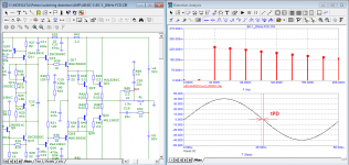
If I understand correctly, you completely negate the Hafler SWDT test for which the amplifier must have a signal propagation delay (tPD) of only 8 ns to pass.
I'm constantly told that I'm testing with unacceptable bursts of sinusoidal signals processed by 100 kHz low-pass filters. At the same time, square-wave testing for measuring SR without any filters is quite acceptable and does not cause any complaints.
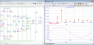
I have shown real amplifiers with 3 times the delay time (tPD = 25nS) than required for SWDT, however, these amplifiers do not have information loss inherent in amplifiers with tPD = 0.2 ... .1.5 µs. I added a comparison of the two models in the introduction.
https://www.diyaudio.com/community/threads/musings-on-amp-design-a-thread-split.366099/post-7266627
prochtite vnimatel'no vstupleniye
If this is not clear, then I can only sympathize.
best regards,
Petr
If I understand correctly, you completely negate the Hafler SWDT test for which the amplifier must have a signal propagation delay (tPD) of only 8 ns to pass.
I'm constantly told that I'm testing with unacceptable bursts of sinusoidal signals processed by 100 kHz low-pass filters. At the same time, square-wave testing for measuring SR without any filters is quite acceptable and does not cause any complaints.
I have shown real amplifiers with 3 times the delay time (tPD = 25nS) than required for SWDT, however, these amplifiers do not have information loss inherent in amplifiers with tPD = 0.2 ... .1.5 µs. I added a comparison of the two models in the introduction.
https://www.diyaudio.com/community/threads/musings-on-amp-design-a-thread-split.366099/post-7266627
prochtite vnimatel'no vstupleniye
If this is not clear, then I can only sympathize.
best regards,
Petr
Last edited:
If this is not clear, then I can only sympathize.
The Church of Holly First Cycle - https://www.diyaudio.com/community/threads/musings-on-amp-design-a-thread-split.366099/post-6853168
Hi all of you, deepening just a bit the "issue" it seems to me that at the end of the day @petr_2009 is obsessioned by a single argument: the SWDT procedure by David Hafler.
Assuming the above is true I had no idea what SWDT test was, but I looked around reading interesting things about it.
Please note that I've no specific technical competence, but I may try to think though.
However I found the following comment interesting:
...
"Matching the straight wire is exactly the same as trimming for minimum distortion.
There were several readers who have questioned the use of a driving amplifier to supply signal for the SWDT. They mistakenly believed that the characteristic of the driving amplifier is to provide a low-impedance signal at a level equal to the level desired in the test amplifier. As long as the drive amplifier supplies a wide-band, fast-risetime signal, its own distortion characteristics do not matter. It could be a noise generator or a spark gap, and the SWDT would still be valid. If the drive amplifier has distortion, then the test amplifier is being tested as to its capability to handle a distorted signal without adding further distortion."
...
"The question of phase shift and time delay from input to output has been raised by several readers. That difference between input and output will prevent a good "null" and will produce residual sound. Obviously, a constant time delay (uniform across the band) will not produce an adverse audible effect. However, the residual from phase shift might mask other distortion components in the SWDT. I prefer to see, therefore, an amplifier design which is sufficiently broadband to minimize time delay in the audio band. This can be accomplished with some phase compensation.
While many people do not believe that phase shift is audible, there is one place where it definitely has an effect, and that is between the two stereo channels. Unless the two sides track phase precisely, there will be problems of stereo imaging. The most practical way to have the left and right channels track is for each of them to have little or no phase shift. The design efforts which make the Hafler XL-280 amplifier perform well on the SWDT give a side-to-side differential null of about 70dB. This preserves the stereo imaging better than on any other units we have examined.
The question has been raised as to why some subjective reviews have not always been consistent with the rankings of the SWDT. Preferences do not necessarily have to correlate with objective tests. A deep wideband "null" may not be necessary for euphonious sound, but it is sufficient to establish that the amplifier has no audible aberrations. Although there is high correlation between a deep "null" and good (accurate) sound, it is conceivable that there can be a poor "null" with pleasant sound. This can happen if the distortions are of a non-offensive nature, such as a small high-frequency roll-off. It can also come from a listener's inaccurate mental reference standard as to what is accurate sound.
There is a philosophical question here. Should an amplifier be pleasant sounding, or should it be accurate even if accuracy is not as pleasant? The SWDT reveals accuracy or the lack of it. It is the only way to assess accuracy directly and objectively with the amplifier operating under normal signal and load conditions. It does this in real time, with a dynamic signal source. It encompasses all forms of distortion. It requires no special instrumentation or skill. If the residual "null" is inaudible, the conclusion that the amplifier is accurate is unequivocal.
Can anyone suggest a more meaningful or practical test of amplifier accuracy?—David Hafler, The David Hafler Company, Pennsauken, NJ"
https://www.stereophile.com/content/manufacturers-comment-0
There are also other interesting articles that seem to confirm the above.
So IMHO it seems that the reasons for being interested are there all.
Of course this does not mean that everyone should automatically accept them as absolute truth.
Therefore my view is that if the one continues to be so insistent and pervasive in wanting to make his truth accepted by everyone breaking the Forum rules then he is wrong at least as much as the others if/when they opposes it on principle, breaking the Forum rules in a different way.
Finally I modestly believe that intellectual honesty (of which I do not doubt at all) and cooperation with a common goal is the right thing to do for Audio, if possible.
Respecting the Forum rules means respecting ourselves. IMHO
Ulogon, this is blatantly off topic. Continue at the dedicated thread, please :Finally I modestly believe that intellectual honesty (of which I do not doubt at all) and cooperation with a common goal is the right thing to do for Audio, if possible.
https://www.diyaudio.com/community/threads/musings-on-amp-design-a-thread-split.366099/
Read carefully dozen or two of first pages to learn everything required about 'intellectual honesty and cooperation' from the peter's side.
And yes, STOP HIJACKING THIS THREAD!
Maybe you all are very right, and maybe it is very probable, but this does not justify to be so rude on an honourable Forum.
My view is the following just as a possibility:
What if by any chance he was right, tomorrow?
offtopic
ulogon, the trouble is that most opponents still believe that the sun revolves around the earth. When you show them with specific examples that everything, on the contrary, is perceived as an insult.
Tombo56, it's only a sentence and fankly it doesn't seem to me that there is a single thread in which someone don't go off topic, it seems inevitable sometimes.questo è palesemente fuori tema
Most of all when then one is called into question.
However, it's enough for me.
Best Regards
Hi Chris,[...]However, much of what petr_2009 emphasizes doesn't apply very closely for audio. The other thing he read that is plain wrong is about an idea by someone else called 'first cycle distortion.'
[...]
What petr_2009 has been doing is using the now freeware microcap simulator to simulate something that is impossible in nature, and treating as though it produces real effects in audio power amps. [...]
It's even more embarrassing: Mr P. doesn't even know how to use Microcap in a proper way. With correct settings of Microcap, I simmed Bod Cordell's EC amplifier and got a THD of 6ppm for the first cycle at 20kHz, (almost) exactly in accordance with real measurements on this amp.
Cheers, E.
Edmond, it confuses me personally how you managed to make an ideal amplifier out of an ordinary amplifier in which there is no signal delay.It's even more embarrassing: Mr P. doesn't even know how to use Microcap in a proper way. With correct settings of Microcap, I simmed Bod Cordell's EC amplifier and got a THD of 6ppm for the first cycle at 20kHz, (almost) exactly in accordance with real measurements on this amp.
p.s.
Edmond, you imposed this test yourself
Attachments
Last edited:
At the level some people design amplifiers everything affects the sound. An attenuator would affect the sound, whatever drives the wire would affect the sound. The sound might already be ruined before it even goes into the wire. That's if you care about things like soundstage width and depth when you listen. Headphones are a bad idea because then the soundstage is confined to the inside of your head. You would need a treated room with electrostatic speakers to really hear if you are nulling out every little detail that can matter to a human. So, I don't completely negate the test. It can probably only get you so far though.If I understand correctly, you completely negate the Hafler SWDT test...
Hello, Mr. Cordell,
Pardon me while I thread-jack back to the subject of your book, 2nd edition. Thank you for your knowledge, readily given in this excellent work. I made some boards for the BC-1 as an attempt to a first amplifier working and have achieved results better than my measurement equipment ( 0.0005% is the noise/THD floor). All worked well until I tried high power with too little heat sinking. One of the output transistors gave up at over 100C case temperature. A prime example of Thud's first law.")
What is your opinion on a surface mount implementation of the IPS/VAS? There are numerous "matched" transistors now available for the IPS, and it looks like some of the DPAK transistors could serve as the pre-drivers and possibly drivers as well. Susumu precision metal film resistors are available for the resistors and C0G caps can be used for the time constants. Does the very much smaller board matter regarding noise? In other words, is there a certain amount of physical space needed to control coupling?
Regarding Chapter 15 on error correction, Figure 15.1 is missing the summing junction labels of S1 and S2 referred to in the the text. I understand the diagram for 15.2, but the transform to get to 15.3 with a difference node feeding a positive feedback node eludes me. To me it looks like 0 times infinity is fed to the output node, ie. (x-x) * (y+y+2y+3y...). The text just says "it is apparent" 15.2 can be redrawn as 15.3. If you have a moment to explain this a bit more, I would appreciate it. It's been almost 50 years since my control systems course.
Pardon me while I thread-jack back to the subject of your book, 2nd edition. Thank you for your knowledge, readily given in this excellent work. I made some boards for the BC-1 as an attempt to a first amplifier working and have achieved results better than my measurement equipment ( 0.0005% is the noise/THD floor). All worked well until I tried high power with too little heat sinking. One of the output transistors gave up at over 100C case temperature. A prime example of Thud's first law.
What is your opinion on a surface mount implementation of the IPS/VAS? There are numerous "matched" transistors now available for the IPS, and it looks like some of the DPAK transistors could serve as the pre-drivers and possibly drivers as well. Susumu precision metal film resistors are available for the resistors and C0G caps can be used for the time constants. Does the very much smaller board matter regarding noise? In other words, is there a certain amount of physical space needed to control coupling?
Regarding Chapter 15 on error correction, Figure 15.1 is missing the summing junction labels of S1 and S2 referred to in the the text. I understand the diagram for 15.2, but the transform to get to 15.3 with a difference node feeding a positive feedback node eludes me. To me it looks like 0 times infinity is fed to the output node, ie. (x-x) * (y+y+2y+3y...). The text just says "it is apparent" 15.2 can be redrawn as 15.3. If you have a moment to explain this a bit more, I would appreciate it. It's been almost 50 years since my control systems course.
Hey @anatech, using ltspice for analog design is invaluable these days for me at least. Thanks for banning the pest so we can focus on the book contents.
I guess Bob's too busy, so I can respond to the BC-1 AFE layout using smd's, the other math stuff on ECC, we'll leave it for him to respond.
Since I worked with Bob to design the BC-1 reference design using THT, I can comment on doing some of the BC-1 AFE in smt, I was thinking the same at one time so that they could potentially be assembled by machine.
Its possible that you get more coupling, but that depands on how the layout is done.
Since Bob specifies 2N5401/5551, Onsemi has them as singles in SOT-23 (MMBT5550LT1/5401LT1) or duals in a SSOT-6 package (FMBM5401/5551). Watch out, the ones from Diodes (DMMT) they are not the same pin-out.
For the VAS, one could use SOT-223 (Diodes DZT5401/5551) or NXP BF722/723, for lower supply V's.
VAS buffers, Q15,16 share a heatspreader with Q13 so its best to stick with the isolated TO-126 devices KSA1381,KSC3503. Also since Q14 is to be placed onto top of one of the o/p devices on the big HS, as the thermal sensor for the Vbe multiplier bias generator, smd is not a good candidate.
Last edited:
Thanks @rsavas. I guess I'll go ahead and give it a try. I have a board that is awaiting my confidence to rise a bit in order to put those SOT-363 parts on by hand. It's not a problem with a stencil and oven, but I expect it to be challenging without the stencil. I was unable to find a reasonable SMD dual for a low-noise input pair. There are lots of the 5401/5551 or 3904/3906 types in "matched" duals, but the only low-noise, really well matched pairs were the AD 2212 part and some quads from THAT. Those are very pricey, especially the AD part. Suggestions welcome.
I caught the Diodes vs. OnSemi pinout before I finished the layout. Had to learn how to make DipTrace components, as the EDA libraries are rarely available in each pinout. Besides, a square block with terminals is not the greatest way to do a schematic.
I caught the Diodes vs. OnSemi pinout before I finished the layout. Had to learn how to make DipTrace components, as the EDA libraries are rarely available in each pinout. Besides, a square block with terminals is not the greatest way to do a schematic.
- Home
- Amplifiers
- Solid State
- Bob Cordell's Power amplifier book