Current flows when there is a potential difference and it flows in proportion to the impedance. Low impedance = lotsa current. Which bit of that is wrong, or is COD one of those nonsense labels that means only what somebody wanted it to in order to achieve some personal goal ??????
Not only you need lots of current, you also need the current to flow where it is needed. You can lower the feedback impedance in a classic long tail pair, Miller compensated, VFA as much as you want, it won't help a iota with the slew rate.
Current flows when there is a potential difference and it flows in proportion to the impedance. Low impedance = lotsa current. Which bit of that is wrong, or is COD one of those nonsense labels that means only what somebody wanted it to in order to achieve some personal goal ??????
It can saturate before supply demanding currents, hence dynamic resistance suddenly increases. All that fancy abbreviations are needed to guard own territory, like dogs do with poles. Any sale needs a story. Job market is not an exception. Invent your own terminology, and you look smarter than competitors.

Hi, can somebody explain the difference between these two IPS...
To better compare them you would need to make them as equivalent as possible - the cascode transistors should be the same type, similarly the VAS-EF and the VAS-CE should match, the currents must match and so on.
You also have additional shunt compensation on the VFA, so not a comparison of equivalents.
Feedback network impedance (ratio is kept) has impact on ULGF and SR in both cases.
Yes, the effect of the load of the feedback network is often not considered but it is real.
(CFA on my picture is really a CFA ? i'm not sure)
Yes it is.
Best wishes
David
Member
Joined 2009
Paid Member
Not only you need lots of current, you also need the current to flow where it is needed. You can lower the feedback impedance in a classic long tail pair, Miller compensated, VFA as much as you want, it won't help a iota with the slew rate.
I'm not sure what you are trying to say. Clearly if you want current to flow in the Cdom you need a low impedance point where the cap is, not some other place such as the fdbk network to an LTP IPS. I think you'd find it helpful to read the amplifier book by Bob, I found it is really good.
Last edited:
Member
Joined 2009
Paid Member
All that fancy abbreviations are needed to guard own territory, like dogs do with poles. Any sale needs a story. Job market is not an exception. Invent your own terminology, and you look smarter than competitors.
Oh, so what I thought, COD is some kind of marketting thing. I'll move on.....
Oh, so what I thought, COD is some kind of marketting thing. I'll move on.....
Here is Cod. Almost like a red herring.

Current flows when there is a potential difference and it flows in proportion to the impedance. Low impe dance = lotsa current. Which bit of that is wrong, or is COD one of those nonsense labels that means only what somebody wanted it to in order to achieve some personal goal ??????
You could say that COD is the marketing version of Ohm's Law
Jan
Last edited:
Bob Cordell speak at BAF2016 https://www.youtube.com/watch?v=V7-27fDgqco
And I am not going to argue with people's personal preferences, however obtained; as I mentioned before, people swear by the most different and completely opposite conceptual amps as you can think of, as being The best Sounding. So that is unfortunately no help to decide which topology is objectively better in terms of accuracy, the original HiFi concept.
So it seems that at this point we just lack the tools to decide that which is coincidental is or is not causal.
So the quest continues....
Jan
Hi Jan ---
I re-found this from 2004 by Dr Sean Olive who rigorously proved this ...... Many/I have seeked to do for a very long time:
"What we've found in general, across age, genre and experience, whether the subject has ear-training or not, is that most people prefer an accurate, neutral monitor. One that maintains the perception of timbre across the frequency spectrum, in the combined direct and reflected source.......... which is an even, accurate, neutral listening experience"
I try to extend this to the whole chain -- record to playback. Those who do not apply this approach of neutrality and accuracy are not IMO pursuing the High-End.
THx-RNMarsh
Last edited:
Great video Bob. It's almost like meeting you.
Hi David,
Thanks!
That video must have spread quickly. I only saw it last night!
Cheers,
Bob
Hi Jan ---
I re-found this from 2004 by Dr Sean Olive who rigorously proved this ...... Many/I have seeked to do for a very long time:
"What we've found in general, across age, genre and experience, whether the subject has ear-training or not, is that most people prefer an accurate, neutral monitor. One that maintains the perception of timbre across the frequency spectrum, in the combined direct and reflected source.......... which is an even, accurate, neutral listening experience"
I try to extend this to the whole chain -- record to playback. Those who do not apply this approach of neutrality and accuracy are not IMO pursuing the High-End.
THx-RNMarsh
Yes I agree, but there is one caveat: you need to test for this in a controlled way. It is easy to see by just looking around and talking to people that left to their own devices and playing with the fruits of their own labor, anything can qualify as 'best sounding'.
Jan
Yes I agree, but there is one caveat: you need to test for this in a controlled way. It is easy to see by just looking around and talking to people that left to their own devices and playing with the fruits of their own labor, anything can qualify as 'best sounding'.
Jan
He did it in a controlled way to determine neutrality and accuracy are what MOST people prefer. How does one know if their design is accurate and neutral? Rather than just liking a particular sound character.
you can do comparison to master/source/real music reference. And, through T & M's. All easier said than done. But accuracy and neutrality are not like preferences for a sound character.
THx-RNMarsh
Last edited:
Help on Open Loop Bandwidth - Cordell example
Hi
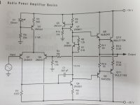
I am studying Cordell's book Audio Power Amplifiers and I have a question on Open Loop Bandwidth.
If you refer to the example amplifier in Figure 2.12 I can't get how the Open-loop bandwith is 613Hz as illustrated in Figure 2.15.
That value should be when the Miller capacitor steps up instead of the input stage load resistance, and I am maybe caught in a Friday evening mind obfuscation, still I can't figure out the math?
Naturally, all the other discussions about open loop bandwidth in the examples that follow this one (so adding current mirror to the LTP etc) are not clear to me either.
Thanks
Hi
I am studying Cordell's book Audio Power Amplifiers and I have a question on Open Loop Bandwidth.
If you refer to the example amplifier in Figure 2.12 I can't get how the Open-loop bandwith is 613Hz as illustrated in Figure 2.15.
That value should be when the Miller capacitor steps up instead of the input stage load resistance, and I am maybe caught in a Friday evening mind obfuscation, still I can't figure out the math?
Naturally, all the other discussions about open loop bandwidth in the examples that follow this one (so adding current mirror to the LTP etc) are not clear to me either.
Thanks

the DC gain is determined by a number of poorly controlled and significantly varying with bias condition, operating point, loaded transistor parameters
fortunately the DC gain and its intercept with the dominant pole, "the open loop bandwidth" is relatively unimportant to audio amplifier performance and stability analysis
so you could prioritize mental effort and accept that there will be some uncertain by order of magnitude DC gain intercept/ "open loop gain corner" and leave it for later (or never)
other circuit optimizations may push up the DC open loop gain but are usually pursued for their linearizing effect on open loop gain without ever setting a DC gain/open loop corner frequency goal or calculating their DC gain effect
the DC gain is determined by a number of poorly controlled and
you could prioritize mental effort and accept that there will be some uncertain by order of magnitude DC gain intercept/ "open loop gain corner" and leave it for later (or never)
other circuit optimizations may push up the DC open loop gain but are usually pursued for their linearizing effect on open loop gain without ever setting a DC gain/open loop corner frequency goal or calculating their DC gain effect
Yeah I eventually went on and left the verification for when I'll have time to work on qucs and a proper simulation. I am fine now with the understanding how the Miller compensation works, poles zeros and all that.
the DC gain is determined by a number of poorly controlled and significantly varying with bias condition, operating point, loaded transistor parameters
fortunately the DC gain and its intercept with the dominant pole, "the open loop bandwidth" is relatively unimportant to audio amplifier performance and stability analysis
so you could prioritize mental effort and accept that there will be some uncertain by order of magnitude DC gain intercept/ "open loop gain corner" and leave it for later (or never)
other circuit optimizations may push up the DC open loop gain but are usually pursued for their linearizing effect on open loop gain without ever setting a DC gain/open loop corner frequency goal or calculating their DC gain effect
This is exactly right. Sorry for the confusion; this aspect of my discussion of open loop gain can probably be better explained and emphasized in my upcoming second edition, maybe even in more than one place in the book to drive the point home. DC open loop gain can actually get crazy high in some of these designs, especially in simulation.
What really counts is the open loop gain at frequencies above the intercept with the DC open-loop gain; like usually 1kHz and above. In other words, the open loop gain that matters is when it is being controlled by the compensation, such as the Miller capacitor, and is falling with frequency.
For all of the same reasons, open-loop bandwidth in these sorts of designs does not matter.
Cheers,
Bob
- Home
- Amplifiers
- Solid State
- Bob Cordell's Power amplifier book