Mooly,
Even a very small dc offset in something like a Compression driver where the voicecoil is very close to an even hung situation with the asymmetric magnetic fields so often the norm and again the asymmetric restorative forces on something with a simple flat Mylar surround would cause measurable distortion in my opinion. How much would be device specific but I would venture easy to measure and document. It may cause little measurable distortion at the power amplifier but significant distortion in the speaker.
Even a very small dc offset in something like a Compression driver where the voicecoil is very close to an even hung situation with the asymmetric magnetic fields so often the norm and again the asymmetric restorative forces on something with a simple flat Mylar surround would cause measurable distortion in my opinion. How much would be device specific but I would venture easy to measure and document. It may cause little measurable distortion at the power amplifier but significant distortion in the speaker.
")
That is my feeling also but as you say, 'by how much'.
Its easy to dismiss 20mv as being of no consequence and yet we chase down 0.000xxx distortion figures when it comes to circuitry. It wouldn't surprise me if a few 10's of millivolts caused more than 0.000xxx 'difference' in the output from the speaker... but how to prove the effect. We can't.
Why not plug in some numbers. Suppose you have a driver with 1% THD at 1w, and assume for fun that it is all second. We also note that a little bit of dc offset will probably cause second harmonic.
1 watt 8 ohms corresponds to 2.83V. Go down 40dB to 28.3mV and you get 0.01% THD that is virtually all soft seconds, which some people like anyway. Forget about 3rd, since it goes down twice as fast with reduced level as second.
In contrast, 0.01% THD from an amplifier may be more audible/annoying because it likely has many more harmonics. Did I do this math right? Just some handwaiving for fun.
Cheers,
Bob
Mooly,
Even a very small dc offset in something like a Compression driver where the voicecoil is very close to an even hung situation with the asymmetric magnetic fields so often the norm and again the asymmetric restorative forces on something with a simple flat Mylar surround would cause measurable distortion in my opinion. How much would be device specific but I would venture easy to measure and document. It may cause little measurable distortion at the power amplifier but significant distortion in the speaker.
But unless you are using active crossovers and tri-amping, a compression driver will not see the dc offset.
Cheers,
Bob
Why not plug in some numbers. Suppose you have a driver with 1% THD at 1w, and assume for fun that it is all second. We also note that a little bit of dc offset will probably cause second harmonic.
1 watt 8 ohms corresponds to 2.83V. Go down 40dB to 28.3mV and you get 0.01% THD that is virtually all soft seconds, which some people like anyway. Forget about 3rd, since it goes down twice as fast with reduced level as second.
In contrast, 0.01% THD from an amplifier may be more audible/annoying because it likely has many more harmonics. Did I do this math right? Just some handwaiving for fun.
Cheers,
Bob
I don't know, -40dB is of course 1%. Unless it's 1% of the already 1% that's assumed. Not sure how this would pan out. But I am not going to lose sleep over it, though it's technically an interesting issue.
jan
every now and then I try to use a Computer Algebra System - GeoGebra here has a weak Symbolic Algebra SW, but its free - its more aimed at middle/high school than EE
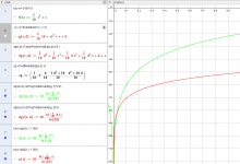
assume a centered VC with 10% full scale 3rd order distortion
add a d_x and expand as a Taylor Series, plot for d= 1/100
(note that the power of each x is dropped by 1 to normalize the distortion number)
see that very low 2nd does dominate, but that the intercept for 3rd crossing 2nd is way down -80dB
Attachments
Last edited:
Did I do this math right? Just some handwaiving for fun.
Cheers,
Bob
I think so.
Speaker theory is something I've never delved into and so I'd never thought about distortion on those terms, that reducing the level from a known value by 'x' amount reduces the distortion from the speaker in proportion.
I don't think the majority of speaker distortion is correlated with amplifier distortion, it is usually inherent in the device and not the signal sent to it. Amplifier distortion can be heard on a speaker if it is high enough but most speakers surely don't need any help to distort.
If you displace the coil with DC, there comes a point where non-linearity and distortion become noticeable I guess. In the limiting case you would get the voice coil at the edge of the field or magnet, and that certainly will mess things up.
But certainly not with 20mV.
Jan
Agreed but it would have to be a lot dc offset.
Hi Mr. Cordell
I have a question on crossover distortion. When you adjust so you have 25mV across the emitter resistor (say running at 100mA idle current with 0.25ohm emitter resistor), is the amount and characteristics of crossover distortion the same with different power transistors?
Thanks
I have a question on crossover distortion. When you adjust so you have 25mV across the emitter resistor (say running at 100mA idle current with 0.25ohm emitter resistor), is the amount and characteristics of crossover distortion the same with different power transistors?
Thanks
Hi Mr. Cordell
I have a question on crossover distortion. When you adjust so you have 25mV across the emitter resistor (say running at 100mA idle current with 0.25ohm emitter resistor), is the amount and characteristics of crossover distortion the same with different power transistors?
Thanks
Hi Stephen,
This is a very good question. The 26mV number is a theoretical number based on ideal transistors. In principle, the total effective emitter circuit ohmic resistance for purposes of the calculation is larger than the 0.25 ohm physical RE you mentioned. There are a couple of reasons for this. First of all, the real transistor has an ohmic component of its emitter resistance. Secondly, there is also an additional ohmic component seen looking into the emitter whose value is roughly the ohmic base resistance divided by the current gain of the power transistor. Finally, the resistance of any base stopper resistors also adds to the effective ohmic base resistance.
The bottom line is that the physical RE is a large percentage of the resistance across which the 26mV should appear, but is not the total amount. For this reason, the point of minimum crossover distortion will often occur at a value of less than 26mV across RE.
With good SPICE models of the output transistors, this phenomena can be investigated, at least in relative terms.
Ultimately, it is best to evaluate amplifier crossover distortion as a function of bias current using a THD analyzer. This can be helped by looking at the THD of the driver node feeding the output transistors, so as to approximately isolate the open-loop distortion of the output stage. For this reason, and for other convenience, when I use a Locanthi T Triple, I center tap the pre-driver and driver emitter resistors so I can see the distortion going into the output stage. That distortion will reflect the distortion created by the negative feedback process to reduce overall amplifier distortion. Its waveshape will be the inverse of the actual distortion being created by the output stage.
Looking at the open-loop distortion of the output stage (under closed-loop conditions) yields a larger distortion number that is easier to see on a distortion analyzer. Perform this at 1kHz to see static crossover distortion.
Cheers,
Bob
Thanks Mr. Cordell for this detail answer.
I am more interested in knowing if I optimize the emitter resistor in both cases, whether there is any difference using MJW3281/1302 vs a smaller transistors TTC5200/TTA1943 in the crossover distortion. Is one pair better than the other pair regarding to crossover distortion.
Note: I know TTC/TTA is lower power transistors and SOA is lower. But I only interested in the crossover region at low listening level.
Thanks
Hi Doug,
Do you not use base stopper resistors on your designs with multiple output pairs?
If not, I am not aware of any alternate ways of ensuring HF stability among multiple output pairs in your book. Do you do anything special to allow you to get away without stoppers, or do you believe that the use of stoppers is not generally needed anyway?
Many, many designers would love to hear that stoppers are not necessary, not the least of whom would be John Curl and myself.
Cheers,
Bob
Like obi-wan said, 'there is another' (way) (I was looking at an adcom, and was looking up base stoppers via google... and found this thread) I have this little technique I've been using recently, and it works great. It works with base stoppers, or in lieu of them. I don't even have to bother measuring, it sounds cleaner, the amp runs cooler under load, and the theory says that is the expected outcome, so...
Last edited:
Like obi-wan said, 'there is another' (way) (I was looking at an adcom, and was looking up base stoppers via google... and found this thread) I have this little technique I've been using recently, and it works great. It works with base stoppers, or in lieu of them. I don't even have to bother measuring, it sounds cleaner, the amp runs cooler under load, and the theory says that is the expected outcome, so...
Hi KBK,
Tell us more!
Cheers,
Bob
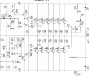
HK uses a paralleled R/L to drive it's outputs - NO basestoppers.
(below) ... HK1.5 signature EF3.
I don't think they match the OP's (according to the manual).
Is the R/L acting as a basestopper at audio frequencies ?
OS
That's a base stopper exactly where it should be: at HF. HF in terms of around the ULGF, not at audio frequencies. An OPS without base stoppers won't oscillate in the audio band. The LC technique may also improve the thermal stability, since there's no base stopper to reflect (divided by beta) in the emitter, at DC.
Not worth the troubles (and cost) today, IMHO.
Hi KBK,
Tell us more!
Cheers,
Bob
I'd love to do so, Bob, but I need a circuit, so i can publish an amplifier with all my tricks, and then they can be public.
I've managed to get the point where you can take any circuit with this overall series of changes, and push it to the point of exploding into flames and there is no sonic (hearable) hint of it falling apart, at all, before you get there.
- Home
- Amplifiers
- Solid State
- Bob Cordell's Power amplifier book