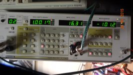
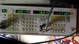
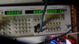
measured data -
Hi..... I too have very specific ideas about low Z pcb layout of power traces and grounds. But I've covered that else where in principle.
if I adhere to dadod's scheme in grounding and using his current pcb layout, I am getting some better numbers than before. I am done for now with listening and assured it is stable under a wide variety of speaker load characteristics. So I went back to test again.
With better grounding paths but still not the best... still on the bench... I am getting better numebrs than before..... Without all the numbers and power levels done over again, just take a look at one quick test i did this evening ref 3 Watts; 1KHz THD+N and THD:
 -101dB thd+N
 -111dB THD That is about .00025%
If anyone doubts how important power and grounds and pickup points are --- with this amp i will produce .015% under same operating conditions but different grounding arrangement.
THx-RNMarsh
Hi..... I too have very specific ideas about low Z pcb layout of power traces and grounds. But I've covered that else where in principle.
if I adhere to dadod's scheme in grounding and using his current pcb layout, I am getting some better numbers than before. I am done for now with listening and assured it is stable under a wide variety of speaker load characteristics. So I went back to test again.
With better grounding paths but still not the best... still on the bench... I am getting better numebrs than before..... Without all the numbers and power levels done over again, just take a look at one quick test i did this evening ref 3 Watts; 1KHz THD+N and THD:
 -101dB thd+N
 -111dB THD That is about .00025%
If anyone doubts how important power and grounds and pickup points are --- with this amp i will produce .015% under same operating conditions but different grounding arrangement.
THx-RNMarsh
Last edited:
Not a criticism , but 3W /1Khz is kind of a "light" load. Pitchfork line buffer
or a LME49600 will do .00003% right out of the box ???
Maybe like 20K/50W/8R ?
One might also note that a multi-pair OPS is pretty much running class A at 3W.
At >6W is where a 5 pair OPS transitions to AB , 1K THD jumps from sub ppm
to single digit PPM. I'm sure this simulated fact would scale to the real test.
The OPS is the major contributor to total THD (at higher power).
OS
If you do them long enough, you may be lucky to find some true golden pinnae. They are likely to be people you least expect like your girlfriend, wife or mother.
An audio friend of mine, who is a gifted carpenter, is one of them. Our group has tested him again and again in DBLT but he again and again identifies which is which correctly, only rarely making a mistake.
Makes beautiful speaker enclosures and horns too.
Jan
Not a criticism , but 3W /1Khz is kind of a "light" load. Pitchfork line buffer
or a LME49600 will do .00003% right out of the box ???
Maybe like 20K/50W/8R ?
One might also note that a multi-pair OPS is pretty much running class A at 3W.
At >6W is where a 5 pair OPS transitions to AB , 1K THD jumps from sub ppm
to single digit PPM. I'm sure this simulated fact would scale to the real test.
The OPS is the major contributor to total THD (at higher power).
OS
Sure. But grounding will still cause thd to be higher if not done right at any power level. It makes a big difference in realizing your sim results or not.
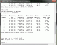
8 Watts:
 .00013% THD [approx -115dB]
 I'll do more testing tomorrow. too late here. Better grounding will help find minimum thd value.
-RNM
Last edited:
I've done one series of DBLTs on someone who had perfect pitch and he was very good.I wonder if some singers who have perfect pitch would be good at dblt, not sure if it would carry over that way. Most musician I have known don't even seem to care about the sound, they just listen differently to the music, they seem more into the composition than the actual sound.
But I don't have sufficient info on musicians to claim they are better than usual.
Most of my true golden pinnae panel were speaker designers or recording engineers ... but I know speaker designers & recording engineers who were deaf too.
For the rest, Jane Public is on average better than Joe Public who is better than HiFi Reviewers (with a VERY few notable exceptions).
Michael Gerzon told me that non-technical people and musicians react differently to poor sound and in nearly 2 decades of DBLTs, I found he was mostly right. They usually criticise the performance if they don't like the sound.
On the other hand, one of the surest signs someone (whether true golden pinnae or layman) really likes the sound is that he will stop talking about it and start talking about the music.
.. and if you think about it, that's how it should be
There's a whole bunch of factors to achieve good reliable DBLTs, most of which, even the false prophets Olive & Co. don't do .. but I could go on forever. eg the victim ALWAYS chooses the music and sets the volume level, tested in isolation bla bla ....
One thing that has puzzled me is why Harman makes such a fuss about DBLTs. What's in it for them? They spend lots of money on things like that hydraulic speaker shuffler and SO most probably doesn't work for free either.
It's not a secret that you can perfectly successfully sell mediocre stuff with the right positioning, brand name and marketing. So, why all that emphasis on objective sound? Or is it another marketing layer I haven't realized yet?
Jan
It's not a secret that you can perfectly successfully sell mediocre stuff with the right positioning, brand name and marketing. So, why all that emphasis on objective sound? Or is it another marketing layer I haven't realized yet?
Jan
So, why all that emphasis on objective sound? Or is it another marketing layer I haven't realized yet?
It's actually hedonic testing.
Not a criticism , but 3W /1Khz is kind of a "light" load. Pitchfork line buffer
or a LME49600 will do .00003% right out of the box ???
Maybe like 20K/50W/8R ?
One might also note that a multi-pair OPS is pretty much running class A at 3W.
At >6W is where a 5 pair OPS transitions to AB , 1K THD jumps from sub ppm
to single digit PPM. I'm sure this simulated fact would scale to the real test.
The OPS is the major contributor to total THD (at higher power).
OS
That is the region where this amp start to live Class A, and distortion start to rise, from 2 W to 5W depends of the bias current set.
One thing I was told by my early mentor was that testing a speaker with another speaker in the room was a very flawed premise as the second set or more sets of speakers though not active at the time are excited by the sound of the speaker under test. This changes the room response and measurable response of the speaker under test. perhaps only at the lower frequencies but it is an effect that is almost always ignored. This is one of the curious things I often think about when I hear about the speaker mechanism that is used by Harman at their Northridge location. The only way I can see this really working would be for the speakers that are not active are removed from the airspace and also that each speaker tested is tested from an identical location in the room for an apples to apples test. Once you start to position each speaker in a preferred location and have each sitting in a different spot I just don't see how you can say that is a properly controlled tests. Any comments on that Kgrlee, you are the man on speaker testing in my eyes.
ps. Happy Fathers day to those other fathers out there.
ps. Happy Fathers day to those other fathers out there.
Last edited:
One thing I was told by my early mentor was that testing a speaker with another speaker in the room was a very flawed premise as the second set or more sets of speakers though not active at the time are excited by the sound of the speaker under test. This changes the room response and measurable response of the speaker under test. perhaps only at the lower frequencies but it is an effect that is almost always ignored. This is one of the curious things I often think about when I hear about the speaker mechanism that is used by Harman at their Northridge location. The only way I can see this really working would be for the speakers that are not active are removed from the airspace and also that each speaker tested is tested from an identical location in the room for an apples to apples test. Once you start to position each speaker in a preferred location and have each sitting in a different spot I just don't see how you can say that is a properly controlled tests. Any comments on that Kgrlee, you are the man on speaker testing in my eyes.
ps. Happy Fathers day to those other fathers out there.
"testing a speaker with another speaker in the room was a very flawed premise was".
Ivor Tiefenbrum from Linn said so.
Pushing the idea a bit further, there should be no body in the room during the tests.
Last edited:
Sure. But grounding will still cause thd to be higher if not done right at any power level. It makes a big difference in realizing your sim results or not.
8 Watts:
View attachment 489600 .00013% THD [approx -115dB]
I'll do more testing tomorrow. too late here. Better grounding will help find minimum thd value.
-RNM
Still very interesting .... Richard. I know it's not Dadod's amp , but my CFA (ND)
transitions from sub to single digit near 7-8W @70ma bias (below). All 3 of my
CFA's do this.
I know what you are saying with the LME49600. I simulated it and my discrete
version of it in a FB loop with an OPAxxx - got 1/2ppm @ 1K .
It all comes down to listening ... you heard Dadod's amp mostly in first watt (did
you "crank it") ?
I've noticed mostly on the CFA's , they "like" my huge 1KVA PS when I "crank" it.
SQ/ soundstage "opens up" considerably. PSRR is the factor here , way less
ripple on the big trafo /100Kuf PS.
The VFA's typically sound the same with my much smaller test supply or with the
big one. The "Blameless" is power supply "blind".
OS
Attachments
One thing I was told by my early mentor was that testing a speaker with another speaker in the room was a very flawed premise.
When the speaker is not electrically damped by a low impedance shorting the terminals, then it becomes a resonator. I suppose it makes sense. The solution? Short the speaker terminals - in this condition a speaker should be fully damped and no more reactive than cupboards or furniture, no?
It's actually hedonic testing.
OK but still I wonder why they do those things? Why not spend the money on positioning and advertising and make a bundle?
Or use it to make larger boxes for the same price - that will increase sales.
"testing a speaker with another speaker in the room was a very flawed premise was".
Ivor Tiefenbrum from Linn said so.
Pushing the idea a bit further, there should be no body in the room during the tests.
Yes, Like the oxygen-free listening room Douglas Self reports about on his site. Another idea that wasn't successful ;-)
Yes, Like the oxygen-free listening room Douglas Self reports about on his site. Another idea that wasn't successful ;-)
Maybe I didn't read this right but how does one breath in an oxygen free listening room?
Not a criticism , but 3W /1Khz is kind of a "light" load. Pitchfork line buffer
or a LME49600 will do .00003% right out of the box ???
Maybe like 20K/50W/8R ?
One might also note that a multi-pair OPS is pretty much running class A at 3W.
At >6W is where a 5 pair OPS transitions to AB ,...............
3W of ClassA requires an output current while still in ClassA of 0.866Apk................transitions from sub to single digit near 7-8W @70ma bias (below).................
6W is 1.225Apk
7W is 1.323Apk
8W is 1.414Apk
An output pair biased to 70mA will give ~0.14Apk of ClassA.
You would need 10pair with a total bias of 700mA to hit your 7W target and just miss your 8W target in ClassA.
Roenders' amp with 3pair biased to 185mA per pair, only manages 4.9A of ClassA.
A 5pr stage biased to 70mA will just miss a 2W ClassA target.
Last edited:
Firstly, modern computers easily output 96KHz sine waves. In a short time that can fry a Zobel, shift your quiescent to unsafe levels depending on design, or fry speakers either directly or due to excess DC offset caused by demodulation. If your amp/speakers can't safely accept 96KHz at full power (or even more with modern super-high samplerates), then you MUST have a good low-pass filter at the input, or have very good faith in the consumer! And yes, this is a realistic danger. Just one driver bug or crappy sequencer effect plugin could burn out a lot of stuff.
Hmmm, that's what we need, something new to worry about. No more ultrasonics from vinyl, unless you're truly stuck in the past, but far worse from misbehaving digital machinery. How big do you think the risk is? How many times have you seen it happen? Presumably there's nothing in theory to stop it happening at 48 kHz? That will make the LP filter design a good deal more challenging.
A decent amp might well be able to accept 96KHz at full power, though it's by no means a certainty; I very often limit full-power testing to 50 kHz. Speakers are IMHO more vulnerable, though I suppose the rising tweeter inductance might save it.
There is so much more than just slew rate, distortion and clipping. Clipping is particularly easy to fix, use diode something like the good old schottky TTL way to prevent the transistor from going to FF region. It's easy to put one diode up and up diode down to replace schottky diode with a good old 1N4149!!! Clamp the collector and you'll never see the waveform sticking!!! Or better yet, like Mr. Self said, don't crank it!!!
Danger, Will Robinson!
Making a clamp that is truly transparent below its intended operating point is a lot harder than it looks. The non-linear diode capacitance is a real problem, especially if it's in parallel with Cdom as in the Baker clamp. Measure the 20 kHz THD before and afte connecting the clamp.
- Home
- Amplifiers
- Solid State
- Bob Cordell's Power amplifier book
