Indeed, that's also what I use for that.
Also allows you to string a bunch of JPGs into one PDF document.
jan
I've tried using Bullzip to print to a stack of another format and drop them into Word one on each page then print the Word doc to PDF using Bullzip which also works.
On a related topic, I didn't think twice when my free Acroread asked to be updated. Now much of the the tools menu is cloud based with a fee, I was quite irritated because I frequently just cut graphs out of data sheets to paste them else where.
Question for Mike
Not trying to start an arguement, but you like Solomon's tutorial and I would like to get your comment on this. In introducing pole splitting he makes this comment...
In my estimation Fig. 20 reverts to looking at the op-amp as two cascaded voltage gain stages with feedback, and in his own words this adds, "considerable insight".
Not trying to start an arguement, but you like Solomon's tutorial and I would like to get your comment on this. In introducing pole splitting he makes this comment...
Considerable insight into the basic way in which the
second stage operates can be obtained by performing a
small-signal analysis on a simplified version of the circuit
as shown in Fig. 20 [10]. A straightforward twonode
analysis of Fig. 20(c) produces the following expression
for Vout.
In my estimation Fig. 20 reverts to looking at the op-amp as two cascaded voltage gain stages with feedback, and in his own words this adds, "considerable insight".
Hi Scott,
Your question is answered here:
http://www.diyaudio.com/forums/soli...lls-power-amplifier-book-416.html#post3583777
Your question is answered here:
http://www.diyaudio.com/forums/soli...lls-power-amplifier-book-416.html#post3583777
Compare LT1166 with discrete Vbe multipliers
Bob, a really useful addition would be to compare the LT1166 bias controller you show in section 27.5 with the advanced biasing topics you discuss in sections 11.5 'Biasing Power MOSFETs' and 14.5 'Output Stage Thermal Design & Stability'.
(This is of great concern to people who have to make loadsa good amps. Peter Walker & Mike Albinson told me they invented Current Dumping cos they wanted to eliminate Bias Tweaking in production.)
The idea of using feedback to do this is very attractive. Unfortunately, what we want is a 'constant voltage' that is 'controlled' by temperature rather than a controlled current.
I've doodled a lot of circuits which looked at the voltage on the output emitter resistors (like some Class A controllers) but they all have a problem that when the amp is delivering zillion Amps, this voltage rises and the 'supa Vbe spreader' tries to stop this. Because of its long time constant, that means the amp is underbiased immediately after a transient.
The 'conventional' Vbe spreader (including the advanced versions in 14.5) tend not to do this.
Such info would be especially valuable if you manage some 'real life' stuff.
Last edited:
Should be ..The 'conventional' Vbe spreader (including the advanced versions in 14.5) tend not to do this.
The 'conventional' Vbe spreader (including the advanced versions in 14.5) tend not to do this if designed properly
Hi Scott,
Your question is answered here:
http://www.diyaudio.com/forums/soli...lls-power-amplifier-book-416.html#post3583777
Dubious utility vs considerable insight your opinion vs Jim's very old statement. In fact his analysis from his figure 20 could be used and the earlier simplifications discarded since they give virtually no insight into the secondary frequency response problems such as right plane zero, etc.
Last edited:
Bob, a really useful addition would be to compare the LT1166 bias controller you show in section 27.5 with the advanced biasing topics you discuss in sections 11.5 'Biasing Power MOSFETs' and 14.5 'Output Stage Thermal Design & Stability'.
(This is of great concern to people who have to make loadsa good amps. Peter Walker & Mike Albinson told me they invented Current Dumping cos they wanted to eliminate Bias Tweaking in production.)
The idea of using feedback to do this is very attractive. Unfortunately, what we want is a 'constant voltage' that is 'controlled' by temperature rather than a controlled current.
I've doodled a lot of circuits which looked at the voltage on the output emitter resistors (like some Class A controllers) but they all have a problem that when the amp is delivering zillion Amps, this voltage rises and the 'supa Vbe spreader' tries to stop this. Because of its long time constant, that means the amp is underbiased immediately after a transient.
The 'conventional' Vbe spreader (including the advanced versions in 14.5) tend not to do this.
Such info would be especially valuable if you manage some 'real life' stuff.
This is a good suggestion, as output stage bias stability is one of my pet interests. I do hope to show more examples and data with the LT1166.
Cheers,
Bob
Dubious utility vs considerable insight your opinion vs Jim's very old statement. In fact his analysis from his figure 20 could be used and the earlier simplifications discarded since they give virtually no insight into the secondary frequency response problems such as right plane zero, etc.
I do not in any way denigrate the second order model; indeed, I said it gives a vivid insight into the workings of the amplifier; however, my point is you do not need the second order analysis in order to design an amplifier.
Provided the minor loop is stable, all one needs is the approximate expressions for forward-path HF gain and the unity gain frequency given by the first order model.
For further illumination, please download this extract from an unpublished paper of mine here:
http://www.diyaudio.com/forums/atta...-power-amplifier-book-miller_compensation.pdf
I'll check it out. I think part of the issue is that in the classic op-amp the compensation capacitor is feedback and I like to consider the forward transfer function before feedback is applied. If you can fully describe the behavior of the classic circuit without EVER using the voltage at the base of the integrator as a state variable, maybe.
This is a good suggestion, as output stage bias stability is one of my pet interests. I do hope to show more examples and data with the LT1166.
Cheers,
Bob
Bob,
Where does this design come into the picture --->
EDN.com/design/consumer/4397264/3/Designing-a-low-distortion-output-stage....
??
Thx-RNMarsh
http://www.edn.com/design/consumer/4401234/The-Class-i-low-distortion-audio-output-stage--Part-3-
Am I the only idiot who can't find Part 4 of this excellent article?
Am I the only idiot who can't find Part 4 of this excellent article?
http://www.edn.com/design/consumer/4401234/The-Class-i-low-distortion-audio-output-stage--Part-3-
Am I the only idiot who can't find Part 4 of this excellent article?
The Class i low-distortion audio output stage (Part 4) | EDN
Could this be a solution? Е. Margan. Add-on current dumping. - Electronics & Wireles World. 1985, Vol. 91, Осtоbег. № 1596. р. 40 ....I've doodled a lot of circuits which looked at the voltage on the output emitter resistors (like some Class A controllers) but they all have a problem that when the amp is delivering zillion Amps, this voltage rises and the 'supa Vbe spreader' tries to stop this. Because of its long time constant, that means the amp is underbiased immediately after a transient.
The 'conventional' Vbe spreader (including the advanced versions in 14.5) tend not to do this.
Attachments
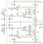
Look here for more about class-I: http://www.diyaudio.com/forums/solid-state/202684-class-i-siblings.html#post2824692
Cheers, E.
Cheers, E.
Bob, a really useful addition would be to compare the LT1166 bias controller you show in section 27.5 with the advanced biasing topics you discuss in sections 11.5 'Biasing Power MOSFETs' and 14.5 'Output Stage Thermal Design & Stability'.
(This is of great concern to people who have to make loadsa good amps. Peter Walker & Mike Albinson told me they invented Current Dumping cos they wanted to eliminate Bias Tweaking in production.)
The idea of using feedback to do this is very attractive. Unfortunately, what we want is a 'constant voltage' that is 'controlled' by temperature rather than a controlled current.
I've doodled a lot of circuits which looked at the voltage on the output emitter resistors (like some Class A controllers) but they all have a problem that when the amp is delivering zillion Amps, this voltage rises and the 'supa Vbe spreader' tries to stop this. Because of its long time constant, that means the amp is underbiased immediately after a transient.
The 'conventional' Vbe spreader (including the advanced versions in 14.5) tend not to do this.
Such info would be especially valuable if you manage some 'real life' stuff.
Kgrlee, you may want to check out David Joffe's article in Linear Audio Vol 6: "Practical Electronic Control of Class AB output stage quiescent Current".
The article describes two control circuits that allow precise setting of quiescent current and also prevent one polarity to turn off when the other conducts.
It does not show the delay behaviour you mention.
jan
Last edited:
http://www.edn.com/design/consumer/4401234/3/Designing-a-low-distortion-output-stage
Or see Linear Audio vol 2 --
This concept is different from the traditional and should be explored - at least in sim. appears to solve the classical issues of biasing and distortion in the output stage.
Would make an excellent addition to the amplifier design book.
-Richard
Last edited:
Look here for more about class-I: http://www.diyaudio.com/forums/solid-state/202684-class-i-siblings.html#post2824692
Cheers, E.
Hi ES -- Have you done a paper or published your class-I concepts and are there any commercial products using this concept?
It appears here about the same time I discovered DIYAudio forum and may have missed it. Just needs the greatest exposure. Glad that Linear Audio and EDN and you are getting the word out so it can get flushed out and optimized.
Thank you,
Richard
Last edited:
Hi Guys
Class-i again? So much for "I'm done with class-i".
In principle, class-i has merit, but the Kendall presentation is flawed, as the threads referred to above detail.
Crossover distortion seems to be dealt with effectively in three ways: eliminating crossover, as in class-A; making the crossover as smooth as possible; or making crossover as fast as possible. Each approach has production amplifier examples that demonstrate its validity. Proof is in the doing.
I designed two circuits to achieve the class-i goal without its detractions, but have to say I prefer simpler approaches.
Have fun
Kevin O'Connor
Hi Bob,
I'm very interested in Fig 11.17 (page 242) - high performance MOSFET amplifier.
I have some questions i want to ask you:
- R21 (100R), why the schematic have R21. The value of R21 is smallest more than R20 (5K6).
The Iin through R20, R21 and they're balanced with Iout by a cascoded with ''helper'' transistor current mirror. Can i change R20, R21 by a PNP medium power trans?! Like 2SA1407, 2SA1381... I think the transistor will set a dynamic impedance Zce, better than a fixed resistors.
- The schematic look like simulation. Have you try to do it, in real life? And if you're did, are they good?! Please take to me more some info. The Iin & Iout have a balance?!
I have some problem with current mirror ''helper'' trans, the Iin & Iout are not true balance (5.6mA for Iin, and 5.9mA for Iout)
I have a plan to do project like this, but simpler. With Hawskford cascode Vas, is the current mirror need cascoded?! Please give me advice, i'm trying to keep the circuit is simple.
Thank you!!!
Attachments
Last edited:
- Home
- Amplifiers
- Solid State
- Bob Cordell's Power amplifier book