No, I'm not forgetting the transistor compensation the VBE multiplier, I do not know if you know this feature in spice, locking all transistors/diodes in a fixed temperature. I lock all transistors for the temperature internal of case, only the output transistors and transistor sensor VBE are unlocked.
I forgot to mention in the previous topic, in my circuit use a triple output (T), pre drives and drives will not in heatsink.
Doing some simulations, found that the culprits by changing the bias current is the change of VBE pre-drives and drives, an increase of only 5°C you will have an increase of 30% in bias current of output transistors.
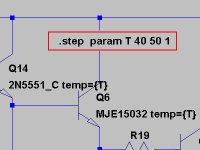
The circuit in Figure is my VBE multiplier for a triple (T), as I am not using ThermalTrak the circuit set for over-compensating in 10°C (40%), this difference in temperature between the transistor output and monitor VBE mounted on heatsink, this according to book D.Self (3 edition).
Thanks for posting this Rafael. I had no idea the temp could be set this way.
Very useful indeed.
Will temp accept a variable which could be stepped?
Last edited:
My question is how do you set the temperature rise over time unless you are actually measuring it in real time? I understand how you can figure the numbers from a data sheet and see the changes but how do you correlate that to room temperatures? It obviously is not directly tied to room temperature as the device temperature will not follow room temperature changes and a rise of 10 degrees C room temp.does not mean that you will have a similar rise in device temperature?
I answered my own question.
.step param tmp LIST 20 25 30 35 40 45 50 55 65
BC557C temp = {tmp}
This can be repeated for any number of transistors or other components.
One can leave the global temp set and temperature sweep selected components.
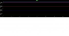
This is a plot of an output tran emitter resistor current sweeping the temp of the output, driver and bias transistors using the above step list.
.step param tmp LIST 20 25 30 35 40 45 50 55 65
BC557C temp = {tmp}
This can be repeated for any number of transistors or other components.
One can leave the global temp set and temperature sweep selected components.
This is a plot of an output tran emitter resistor current sweeping the temp of the output, driver and bias transistors using the above step list.
Attachments
Last edited:
I noticed that in the simulation,variation of temperature in LTP and VAS is little significant change to the bias of the output transistors. You're right, two heatsinks and two vbe multiplier solve the problem, think you used TO-126 for pre-drives.One of my favorite approaches is to use two transistors in the bias spreader. One on the heatsink and one on a board-mounted heat spreader bar onto which are also mounted the pre-drivers and drivers.
I answered my own question.
.step param tmp LIST 20 25 30 35 40 45 50 55 65
BC557C temp = {tmp}
This can be repeated for any number of transistors or other components.
One can leave the global temp set and temperature sweep selected components.
This is a plot of an output tran emitter resistor current sweeping the temp of the output, driver and bias transistors using the above step list.
I too did, but simple see the 1 figure.
Do do not forget if you do not use ThermalTrak (see figure 2) should over-compensate the vbe multiplier. I use transistors TO-3P they do not have to tab metallic for put transistor/sensor, I put the transistor in the heatsink and use the 3 line of graph (12°C over-compensate).
Attachments
I noticed that in the simulation,variation of temperature in LTP and VAS is little significant change to the bias of the output transistors. You're right, two heatsinks and two vbe multiplier solve the problem, think you used TO-126 for pre-drives.
Hi Rafael,
Your observation is correct, especially if the bias spreader is not much affected by the VAS current.
Yes, I usually like to use TO-126 for predrivers, as they can dissipate some power and they can be mounted to a heat sink or heat spreader.
Note that with a Triple, one can also choose to mount the drivers on the main heat sink and keep the predrivers on the board with their own Vbe multiplier transistor (as part of a two-transistor bias spreader) and have that transistor mounted back-to-back with one of the predrivers (instead of using a heat spreader to mount the two predrivers and the Vbe multiplier). This assumes that the two predriver transistors are at about the same temperature. The extra heat sinking effect of the Vbe multiplier mounted to one of the predrivers will introduce a little bit of error into this assumption.
Cheers,
Bob
My question is how do you set the temperature rise over time unless you are actually measuring it in real time? I understand how you can figure the numbers from a data sheet and see the changes but how do you correlate that to room temperatures? It obviously is not directly tied to room temperature as the device temperature will not follow room temperature changes and a rise of 10 degrees C room temp.does not mean that you will have a similar rise in device temperature?
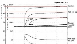
Hi Kindhornman, I considered increases of temperature over time taking into account the dissipation the heatsink, which increases the internal temperature of case (aprox 45°C - 50°C), but this internal temperature of case varies with the external ambient temperature.
Was just an example to show its effect on output trasistores, in general, transistor have temperature above the internal temperature, if you consider the power dissipated, can be calculated using the value from the datasheet C°/W.
An amplifier is a time invariant system whose output depends only on its present input.
Most thermal effects currently discussed in this thread are submitted to the negative feedback linearisation.
For long, my concern was if thermal distorsion could occur in the input stage.
Peufeu and Gérard Perrot (papers and patents in english are available at Memory Distortion Philosophies ) have designed nice linear input circuits where the most crucial transisors work under constant power conditions.
However these authors failed to formerly demonstrate that the conventionnal input stages really suffer from thermal or memory (sliding offset could be seen as a memory effect).
My tests tend to show that these effects are insignificant and that conventional amplifier inputs are time invariant.
Is it not as easy to use diode connected transistors ( same as predriver ), put them in close thermal contact with predriver and in serie with the Vbe multiplier of the others ( driver and output transistors).Hi Rafael,
Your observation is correct, especially if the bias spreader is not much affected by the VAS current.
Yes, I usually like to use TO-126 for predrivers, as they can dissipate some power and they can be mounted to a heat sink or heat spreader.
Note that with a Triple, one can also choose to mount the drivers on the main heat sink and keep the predrivers on the board with their own Vbe multiplier transistor (as part of a two-transistor bias spreader) and have that transistor mounted back-to-back with one of the predrivers (instead of using a heat spreader to mount the two predrivers and the Vbe multiplier). This assumes that the two predriver transistors are at about the same temperature. The extra heat sinking effect of the Vbe multiplier mounted to one of the predrivers will introduce a little bit of error into this assumption.
Cheers,
Bob
JPV
Is it not as easy to use diode connected transistors ( same as predriver ), put them in close thermal contact with predriver and in serie with the Vbe multiplier of the others ( driver and output transistors).
JPV
The predriver Vbe multiplier transistors are not diode-connected transistors in what I described. They comprise a complete Vbe multiplier that is in series with the Vbe multiplier for the output transistors. I believe I covered this in my book. Works great.
Cheers,
Bob
I thought of the addendum ... and was actually fantasizing about a BCEvo Amp PCB, BCchipamp PCB and step-by-step test track CD included with the next issue of the book ... but that's a bit presumptuous on my part
Let's just get a quick, simple, easy PCB going!
Would a new thread be in order?

Hi Jeff,
Were it not for copyright issues, I would pretty much know what musical cuts to put on an "audition" CD for listening to amplifiers. Peter Smith and I have made up a couple of such CDs that we often carry around with us at audio shows like RMAF. Of course, everyone has their own favorites. One thing that is remarkable at these shows is how many rooms are playing perfectly awful material to demonstrate their systems. What a pity.
Cheers,
Bob
"Audition CD" should have Samuel Barber's Adagio for Strings as performed by the London chamber orchestra.
Hi Mike,
There is so much good stuff out there, from many different genres!
One of my favorites is a live cut of "Hotel California" by the Eagles. Another one is "Ghetto of my Mind" from Rickie Lee Jone's Flying Cowboys album. Yet another is "New Favorite" on a live Allison Kraus & Union Station album.
Cheers,
Bob
Is it not as easy to use diode connected transistors ( same as predriver ), put them in close thermal contact with predriver and in serie with the Vbe multiplier of the others ( driver and output transistors).
JPV
Even if you have perfect thermal contact, it takes time for the short-term power dependent temp changes to get from the die to the outside world.
See attached. Perfect thermal stability (long term), still what some would call 'thermal memory'.
jan
Attachments
Bob, you should note in your book that all current sources are negative feedback current sources since they use negative feedback in order to function.
What you refer to as the negative feedback current source is, in fact, an amplified negative feedback current source.
The amplified negative feedback current source would be my first choice for both the TAS and the TIS, as its output impedance is very high, approaching that of a cascode source.
You can read more on current sources and much else besides in the late great Hans Camenzind's book which he made available free to download here:
http://www.designinganalogchips.com/...nalogchips.pdf
The book is also available to buy from Amazon. Highly recommended.
Bob, you should note in your book that all current sources are negative feedback current sources since they use negative feedback in order to function.
What you refer to as the negative feedback current source is, in fact, an amplified negative feedback current source.
The amplified negative feedback current source would be my first choice for both the TAS and the TIS, as its output impedance is very high, approaching that of a cascode source.
You can read more on current sources and much else besides in the late great Hans Camenzind's book which he made available free to download here:
http://www.designinganalogchips.com/...nalogchips.pdf
Hi Mike,
When you say that all current sources are feedback current sources, are you referring to, e.g., the emitter degeneration in a current source formed by a CE transistor whose base is fed a reference voltage, as from a zener?
Similarly, do you consider a current mirror fed on one side from a voltage source through a current-setting resistor to be a feedback current source?
I agree that the "amplified" two-transistor current source I discuss on pp. 38-40 in my book is a good choice for the tail current of the input stage (IPS) and the load for the VAS in a single-ended VAS amplifier.
Thanks for providing that link. I had the pleasure of meeting Hans several times at ISSCC conferences.
Cheers,
Bob
The predriver Vbe multiplier transistors are not diode-connected transistors in what I described. They comprise a complete Vbe multiplier that is in series with the Vbe multiplier for the output transistors. I believe I covered this in my book. Works great.
Cheers,
Bob
I understand that. My questions is : do you think that using diodes (same as transistor) as explaine will give the same performance as your circuit;
The reason why I am asking this is : I use the lme49810 as driver. It has two diodes in series in the vas and has a predriver on chip. This is very handy to make a triple because the predriver is on chip and the 2 diodes must be in very good thermal contact on chip and I hope mached to the predriver.
In this way, the vbe compensation to be implemented will be for the driver and output transistor only.
JPV
Even if you have perfect thermal contact, it takes time for the short-term power dependent temp changes to get from the die to the outside world.
See attached. Perfect thermal stability (long term), still what some would call 'thermal memory'.
jan
Nice picture;
This is true for any kind of Vbe multiplier.
See my post here above for thermal compensation of predriver in a triple using the lme49810 as predriver
JPV
- Home
- Amplifiers
- Solid State
- Bob Cordell's Power amplifier book