dear sir
greetings reading your book i decided to make your higher version triple ef amplifier 560 watts in 2 ohms can
1 2SA1381 and 2SC3503BE SUBSTITUTED mje 340 mje 350 or 2sa1837 2sc4793
warm regards
andrew lebon
Hi Andrew,
I'm assuming that you are referring to the amplifier in Figure 3.14, where 2SC3503/2SA1381 were used as pre-drivers, MJE15032/33 were used as drivers, and four pair MJL21193/4 were used as output devices. All of the amplifiers in Chapter 3 were thoroughly simulated, but were shown and discussed only for illustrative purposes. In some cases the scaling for higher power was done illustratively but not necessarily in a way that was safe for operation at the higher powers into 2 ohms. Thus, caution is required in actually building and running these amplifiers into the lower-impedance loads. This applies especially to the number of output pairs and to the size of the driver transistors.
If you were going to run this amplifier into 2 ohms at 560 watts, in addition to increasing the number of output pairs, you might be wise to increase the size of the drivers to TO-247 power devices
I inadvertantly hit the submit button before finishing.
You might consider using larger drivers like the NJL3281/NJL1302. For that matter, you might consider using ThermalTrak MJL3281/MJL1302 for output devices. You might even want to beef up the pre-drivers to MJE15032/33.
As you know, peak output currents get very high in a 560-watt amplifier at 2 ohms using 64-volt rails - on the order of 30 amps, depending on actual rail voltage at the time of a large transient. This would be 7.5 amps per output transistor, where current gain for the MJL3281 may have drooped to 45 (many other power transistors will be worse), resulting in peak driver current of about 700 mA. SOA of every transistor in the output stage must be evaluated carefully for a big amplifier driving 2 ohms.
If fairly continuous operation with fairly compressed material is to be anticipated running into 4 ohms, more than 4 pairs of output devices is desirable for reliability and thermal considerations - perhaps 6 pairs or more.
You also need to give a lot of thought to protection schemes, especially in big amplifiers.
Cheers,
Bob
q5 2n5551
sir i am also interested in building 3.14.but i noticed that most amplifier use to126 in thermal tracking.is it possible also for to92 case be used in thermal tracking for 200w at 8 ohms?suppose i change this one with a to126 casing
do i need to change the value of r8 and r7?
regards,
joel
I inadvertantly hit the submit button before finishing.
You might consider using larger drivers like the NJL3281/NJL1302. For that matter, you might consider using ThermalTrak MJL3281/MJL1302 for output devices. You might even want to beef up the pre-drivers to MJE15032/33.
As you know, peak output currents get very high in a 560-watt amplifier at 2 ohms using 64-volt rails - on the order of 30 amps, depending on actual rail voltage at the time of a large transient. This would be 7.5 amps per output transistor, where current gain for the MJL3281 may have drooped to 45 (many other power transistors will be worse), resulting in peak driver current of about 700 mA. SOA of every transistor in the output stage must be evaluated carefully for a big amplifier driving 2 ohms.
If fairly continuous operation with fairly compressed material is to be anticipated running into 4 ohms, more than 4 pairs of output devices is desirable for reliability and thermal considerations - perhaps 6 pairs or more.
You also need to give a lot of thought to protection schemes, especially in big amplifiers.
Cheers,
Bob
sir i am also interested in building 3.14.but i noticed that most amplifier use to126 in thermal tracking.is it possible also for to92 case be used in thermal tracking for 200w at 8 ohms?suppose i change this one with a to126 casing
do i need to change the value of r8 and r7?
regards,
joel
Hi,
This is a bit out of the scope of Bob's book but I must make a decision on my pcb. Help is needed")
I will place a copperplane on layer 3 (top to down count on a 4 layer pcb). I will divide this plane in 3 sectors. One for signal ground (near input and feedback) one for common ground (like ref for zeners, etc) and one for decoupling ground near the rails since it will return rubbish from the decoupling capacitors.
The tracks are layed-out to make those 3 islands not interfere with each other (they are more than 10 mm apart).
First...is this usefull? Second... there is still quite some surface where none of the islands have filled that layer. I think it would be nice to pour also there some ground polygon, maybe for shielding only? In that case, should I connect it to common ground or decoupling ground?
Stack:
Layer1 : V rails, nodes which are not crucial (I hope I made the right choices here).
Layer2 : idem.
Layer3 : copper plane (see text above).
Layer4 : input circuit nodes, fedback circuit nodes (low V swing side), IPS to VAS connection...
(there is no OPS in the design yet)
I have read some controversy about planes so I am worried about making it right.
If someone is interested in seeing the pcb I can upload it in pdf ... maybe in another thread or so... let me know.
Thnx
Olivier
This is a bit out of the scope of Bob's book but I must make a decision on my pcb. Help is needed
I will place a copperplane on layer 3 (top to down count on a 4 layer pcb). I will divide this plane in 3 sectors. One for signal ground (near input and feedback) one for common ground (like ref for zeners, etc) and one for decoupling ground near the rails since it will return rubbish from the decoupling capacitors.
The tracks are layed-out to make those 3 islands not interfere with each other (they are more than 10 mm apart).
First...is this usefull? Second... there is still quite some surface where none of the islands have filled that layer. I think it would be nice to pour also there some ground polygon, maybe for shielding only? In that case, should I connect it to common ground or decoupling ground?
Stack:
Layer1 : V rails, nodes which are not crucial (I hope I made the right choices here).
Layer2 : idem.
Layer3 : copper plane (see text above).
Layer4 : input circuit nodes, fedback circuit nodes (low V swing side), IPS to VAS connection...
(there is no OPS in the design yet)
I have read some controversy about planes so I am worried about making it right.
If someone is interested in seeing the pcb I can upload it in pdf ... maybe in another thread or so... let me know.
Thnx
Olivier
sir i am also interested in building 3.14.but i noticed that most amplifier use to126 in thermal tracking.is it possible also for to92 case be used in thermal tracking for 200w at 8 ohms?suppose i change this one with a to126 casing
do i need to change the value of r8 and r7?
regards,
joel
The use of a thermal tracking transistor in a TO-126 case is mainly a matter of physical design and mounting convenience. It is entirely reasonable to put a TO-92 into a small hole in the heat sink and get satisfactory results. In some cases, there may be a bit better thermal coupling to the heat sink with the T0-126 because of its thermal mounting tab. The resistors always need to be adjusted a bit for the particular thermal tracking transistor being used.
Cheers,
Bob
thank you.
The use of a thermal tracking transistor in a TO-126 case is mainly a matter of physical design and mounting convenience. It is entirely reasonable to put a TO-92 into a small hole in the heat sink and get satisfactory results. In some cases, there may be a bit better thermal coupling to the heat sink with the T0-126 because of its thermal mounting tab. The resistors always need to be adjusted a bit for the particular thermal tracking transistor being used.
Cheers,
Bob
Hi Bob
Have a few questions.
How accurate are the Inferring loop gain and Measuring loop gain methods on page 415 and 416 in your book, are they accurate enough for phase and gain margin check?
I can see that both methods arent really accurate below 10 kHz but above they seem to give good results, OLG gain crossover and LG unity gain both match.
However, if one uses TMC is there something we need to be aware of or do these 2 methods of determining OLG and LG work equally well for TMC, disregarding the issue of inaccuracies below 10 kHz?
The use of a thermal tracking transistor in a TO-126 case is mainly a matter of physical design and mounting convenience. It is entirely reasonable to put a TO-92 into a small hole in the heat sink and get satisfactory results. In some cases, there may be a bit better thermal coupling to the heat sink with the T0-126 because of its thermal mounting tab. The resistors always need to be adjusted a bit for the particular thermal tracking transistor being used.
Cheers,
Bob
2N6716/2N6727 from Central Semi comes in a TO-237 case, TO-92 with a tab. I measure Hfe ~200 for the ones I have.
amp bias pot
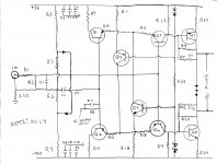
I've learned there a lot of very sharp amp builders following this thread. would one you take a stab at how-to & where put a bias pot on the attachment?
I developed the drawing studying the driver boards many hours. I can post a parts list if necessary.
Thanks in advance for your help, Tony
I've learned there a lot of very sharp amp builders following this thread. would one you take a stab at how-to & where put a bias pot on the attachment?
I developed the drawing studying the driver boards many hours. I can post a parts list if necessary.
Thanks in advance for your help, Tony
Attachments
Last edited:
I've learned there a lot of very sharp amp builders following this thread. would one you take a stab at how-to & where put a bias pot on the attachment?
I developed the drawing studying the driver boards many hours. I can post a parts list if necessary.
Thanks in advance for your help, Tony
Well you can put a bias pot in series with the diode bias string. But why not use a transistor bias spreader instead?
David.
Hi,
This is a bit out of the scope of Bob's book but I must make a decision on my pcb. Help is needed
I will place a copperplane on layer 3 (top to down count on a 4 layer pcb). I will divide this plane in 3 sectors. One for signal ground (near input and feedback) one for common ground (like ref for zeners, etc) and one for decoupling ground near the rails since it will return rubbish from the decoupling capacitors.
The tracks are layed-out to make those 3 islands not interfere with each other (they are more than 10 mm apart).
First...is this usefull? Second... there is still quite some surface where none of the islands have filled that layer. I think it would be nice to pour also there some ground polygon, maybe for shielding only? In that case, should I connect it to common ground or decoupling ground?
Stack:
Layer1 : V rails, nodes which are not crucial (I hope I made the right choices here).
Layer2 : idem.
Layer3 : copper plane (see text above).
Layer4 : input circuit nodes, fedback circuit nodes (low V swing side), IPS to VAS connection...
(there is no OPS in the design yet)
I have read some controversy about planes so I am worried about making it right.
If someone is interested in seeing the pcb I can upload it in pdf ... maybe in another thread or so... let me know.
Thnx
Olivier
Hi Olivier,
First of all, you are ahead of the game by using a four-layer board. This gives you the options to do a better job, especially in terms of using ground planes, or as you are proposing, ground islands.
I wasn't quite sure what you meant by "idem" for Layer 2. I don't think ground plane and power plane choices ar an exact science, but it sound like you are on the right track. The key is, always know ehere the currents are flowing, and manage that current if necessary. Of course, for a signal ground plane, it is best if no current flows in it. Also, always be mindful of where power supply bypass capacitors go to ground, as their low impedance at high frequencies can sometimes destroy one's star ground topology. Also bear in mind that even a small series resistance can be very effective in breaking a ground loop or directing current flow.
Best regards,
Bob
Hi Bob
Have a few questions.
How accurate are the Inferring loop gain and Measuring loop gain methods on page 415 and 416 in your book, are they accurate enough for phase and gain margin check?
I can see that both methods arent really accurate below 10 kHz but above they seem to give good results, OLG gain crossover and LG unity gain both match.
However, if one uses TMC is there something we need to be aware of or do these 2 methods of determining OLG and LG work equally well for TMC, disregarding the issue of inaccuracies below 10 kHz?
Hi Neutrality,
These methods are both quite good and quite accurate where it counts - at the higher frequencies where issues of phase margin and gain margin come into play. However, these methods only assess the loop gain of the global feedback loop. This is mainly what most people care about in most conventional designs. However, this technique does not take into account the total amount of loop gain seen enclosing a given local device or circuit when there is additional local feedback - like TMC, or TPC or error correction.
So if all you care about is the phase and gain margin of the global feedback loop, then these methods do work for things like TMC. Unfortunately, just the global feedback is not the whole story for TMC or TPC.
Cheers,
Bob
Hi Bob,
what kind of wattage rating would you recommend for a output coil's damping resistor, if I were to change the original resisitor (which is 10ohm / 3W) to 1 ohm resisitor (based on your book)? Given the lesser ringing with 1ohm resistor, do you think that 12W resistor would be adeguate? I think the coil is 2,2µH (from boards marking, either 2,2 or 22µH), I cannot measure it alone but in the circuit I get reading 0,75µH from coil's legs. The amp is quite powerfull, approx. 600w/8ohm, 1050w/4ohm.
Ho much does this lower the output impedance, I quess it does at some degree?
Regards,
Legis
Last edited:
Hi Neutrality,
These methods are both quite good and quite accurate where it counts - at the higher frequencies where issues of phase margin and gain margin come into play. However, these methods only assess the loop gain of the global feedback loop. This is mainly what most people care about in most conventional designs. However, this technique does not take into account the total amount of loop gain seen enclosing a given local device or circuit when there is additional local feedback - like TMC, or TPC or error correction.
So if all you care about is the phase and gain margin of the global feedback loop, then these methods do work for things like TMC. Unfortunately, just the global feedback is not the whole story for TMC or TPC.
Cheers,
Bob
I get what you are saying, that for TMC,TPC etc. it doesnt show the whole picture, but for determining if you have enough LG phase and gain margin on a TMC design. it should be ok?
If it isnt good enough for determining LG phase and gain margin on TMC designs, what else could be used instead?
Last edited:
for TMC it is better to measure the loop gain inside "both" of the TMC loops, measuring the gain around the output Q - since it is the slow output Q and added phase shift with Cload that give the most stability problems
http://www.diyaudio.com/forums/soli...lls-power-amplifier-book-134.html#post2420438
and my next post a little further down shows how measuring the "global" loop misleads, and how measuring "inside the loops" gives a more useful picture
http://www.diyaudio.com/forums/soli...lls-power-amplifier-book-134.html#post2420438
and my next post a little further down shows how measuring the "global" loop misleads, and how measuring "inside the loops" gives a more useful picture
Interesting, but looks like a difficult way to do it.
EDIT : Also, the fact that their COULD be stability problems with TMC or TPC, bothers me. Is it really worth it to reduce THD-20 from 0.00XXXX% to 0.000XXX% when there is a higher risk on instability? In both cases we are already at such low levels of THD that no one would be able to tell the difference.
EDIT : Also, the fact that their COULD be stability problems with TMC or TPC, bothers me. Is it really worth it to reduce THD-20 from 0.00XXXX% to 0.000XXX% when there is a higher risk on instability? In both cases we are already at such low levels of THD that no one would be able to tell the difference.
Last edited:
the stepped delay element just tests the "robustness" of the loop gain "picture" implied stability - shows a unwelcome stability "surprise" if you rely on just measuring the global loop gain with TMC
once you know that the "simple Middlebrook" loop gain probe "inside" the TMC loops gives a "fair" picture of stability then you can just use it by itself
as I do when I keep pointing to the essential similarity of TMC and 2-pole compensation
due to the potential for "linearizing" the diff pair due to higher gain I prefer 2-pole - and the global loop gain measurement gives good stability indication
Last edited:
- Home
- Amplifiers
- Solid State
- Bob Cordell's Power amplifier book