PMA said:Frankly speaking, I expected this result and the method used. Also, I beliveve, that in case you will explore quite nasty class AB stage inside ideal math block NFB, you will wind f1 + f2 CCIF IM reduction.
I do not build nasty Class-AB stages
") .
.However, I will give it a try with a reasonable Class-AB stage using RET output devices with RE = 0.22 ohm, biased with 26 mV across each RE, and driving a 4 ohm load.
Cheers,
Bob
I assume, that in my case, there were 2 factors:
1) output stage had inherently very low distortion,
2) the real opamp was not that good to help for f1 + f2 component.
I originally assumed that the opamp would have helped in my simulation.
Most probably this would be a question of implementation of both output stage and input stage + VAS.
Regards,
Pavel
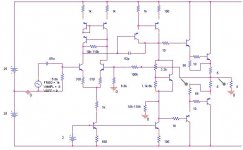
I have made some measurements on crossover distortion versus feedback factor at DC. I have 2 pots, one adjusting bias and the other adjusting feedback factor going from 35dB at DC and reasonably flat on audio range and 60dB at DC with low open loop bandwidth.
Edit: more on feedback pot: it is actually a stereo log 100K pot in series with resistors. It adjusts resistive loading of LTP and VAS going from less than 10k to some 115k (cheap pot). Gain-bandwidth product remains nearly the same when adjusting feedback, just dominant pole frequency changes.
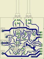
Schematic:
Edit: more on feedback pot: it is actually a stereo log 100K pot in series with resistors. It adjusts resistive loading of LTP and VAS going from less than 10k to some 115k (cheap pot). Gain-bandwidth product remains nearly the same when adjusting feedback, just dominant pole frequency changes.
Schematic:
Attachments
Compounding Harmonics
This might be a silly question and may not merit a thread of it’s own so decided to post it here which might be OT to some extent.
So here we go… Which would you think is a better system considering a lineamp + the amp? Both having predominant 2nd harmonic or one having 2nd and the other 3rd?
The last option seems to be a better marriage to avoid compounding the predominant harmonic. Anyone having experience on this?
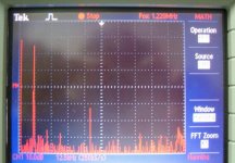
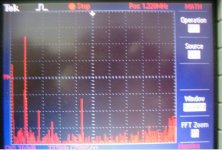
8bit, 10dB/div, I guess distortion products are not below dynamic range.PMA said:Hi Adam,
what is the scope A/D resolution in bits? And Y axis is 10dB/div ?
So the result for 60dB FB was about 5dB worse than that for 40dB FB?
[/B]
It looks exactly like this. Keep in mind that 10kHz is already higher than open loop bandwidth in both cases and in both cases FB at 10kHz is probably around 25dB. FB at low frequency is 60dB and 40dB.
regards
darkfenriz said:Keep in mind that 10kHz is already higher than open loop bandwidth in both cases and in both cases FB at 10kHz is probably around 25dB. FB at low frequency is 60dB and 40dB.
regards
I keep it in mind, that's why the results are interesting, it is close to many real world designs.
Adam,
though I cannot attach the image, I have my web:
though I cannot attach the image, I have my web:
An externally hosted image should be here but it was not working when we last tested it.
PMA said:Adam,
though I cannot attach the image, I have my web:
<image removed by moderating team>
Pavel,
Nice plot. Is this a SPICE simulation?
How much NFB was in place at dc here?
Thanks!
Bob
19+20kHz IMD spectrum
Hi Bob,
You were once a proponent of the multi-tone IMD spectrum, which allows separation of the odd and even products. I remember Erno Borbely made an IMD tester that provided the 19+20kHz IMD as well as a three-frequency multi-tone IMD, I think it was 9kHz, 10.05kHz and 20kHz. His was an all-analog tester, it was an article in The Audio Amateur (now audioXpress) magazine, but it might be quite easy to implement in Red Book digital as well. Lately you have only mentioned the 19+20kHz IMD. Have you abandoned multi-tone for some reason?
Also, is anyone on the post taken it upon themselves to be the scribe to keep a list of the best-practices or lessons-learned, whereby each section of a bipolar or MOSFET amp design is "finalized" by agreement of most of the experienced designers. For instance, it seems to be in almost in universal agreement that a Class-AB output stage design should have 15-25mA bias per device, a MOSFET much higher bias, etc.
Best Regards,
Chuck
Re: 19+20kHz IMD spectrum
Hi Chuck,
Yes, that is right. The AES paper describing the MIM tester and its results can be found under the published papers tab on my web site at www.cordellaudio.com.
The MIM test was a special kind of triple-beat IM test that was fully in-band with respect to both the test signal and the measured IM products. The idea was to fold the odd and even-order products down into the audio band at about 1 kHz, where they could easily be separated from the higher-frequency test signals with low-cost equipment.
The MIM test sought to overcome the inherent weakness of the two-tone CCIF test, which was only sensitive to even-order distortion insofar as distortion products folded down to the 1 kHz range.
The MIM test was developed in the early Eighties, when audio spectrum analyzers like the HP 3580A were very expensive. Nowadays, PC-based spectrum analyzers with better dynamic range than the 3580A are available at very reqasonable prices. As a result, the need for MIM is less, since the CCIF test gives all the odd-order distortion information you want as long as you view its results on a spectrum analyzer. That is why, nowadays, I prefer the CCIF IM test. Because John Atkinson regularly uses it and publishes those results in Strereophile, it provides a very useful common ground for comparing distortion behavior in a detailed way.
Because of the way MIM distortion is defined (spectral amplitude compared to a sinewave with equivalent p-p amplitude), and because the test's peak rate of change (slew rate) is only about 2/3 that of a full-scale 20 kHz sinusoid, the absolute numbers that are delivered by the MIM test are smaller than those delivered by DIM-30 or even THD-20 at the same signal level. However, its measurement floor is much, much lower, on the order of < 0.0001% from an inexprensive box. In comparison, the noise floor for DIM-30 using a spectrum analyzer with 90 dB dynamic range was a rather high 0.035%.
It is notable that the DIM distortion percentage is the amplitude of the distortion spectra as compared to the amplitude of the smaller 15 kHz portion of the test signal, whose p-p value is only 1/5 that of the total test signal. There is thus a 14 dB boost in numbers from this definition aspect alone.
Cheers,
Bob
chascode said:Hi Bob,
You were once a proponent of the multi-tone IMD spectrum, which allows separation of the odd and even products. I remember Erno Borbely made an IMD tester that provided the 19+20kHz IMD as well as a three-frequency multi-tone IMD, I think it was 9kHz, 10.05kHz and 20kHz. His was an all-analog tester, it was an article in The Audio Amateur (now audioXpress) magazine, but it might be quite easy to implement in Red Book digital as well. Lately you have only mentioned the 19+20kHz IMD. Have you abandoned multi-tone for some reason?
Also, is anyone on the post taken it upon themselves to be the scribe to keep a list of the best-practices or lessons-learned, whereby each section of a bipolar or MOSFET amp design is "finalized" by agreement of most of the experienced designers. For instance, it seems to be in almost in universal agreement that a Class-AB output stage design should have 15-25mA bias per device, a MOSFET much higher bias, etc.
Best Regards,
Chuck
Hi Chuck,
Yes, that is right. The AES paper describing the MIM tester and its results can be found under the published papers tab on my web site at www.cordellaudio.com.
The MIM test was a special kind of triple-beat IM test that was fully in-band with respect to both the test signal and the measured IM products. The idea was to fold the odd and even-order products down into the audio band at about 1 kHz, where they could easily be separated from the higher-frequency test signals with low-cost equipment.
The MIM test sought to overcome the inherent weakness of the two-tone CCIF test, which was only sensitive to even-order distortion insofar as distortion products folded down to the 1 kHz range.
The MIM test was developed in the early Eighties, when audio spectrum analyzers like the HP 3580A were very expensive. Nowadays, PC-based spectrum analyzers with better dynamic range than the 3580A are available at very reqasonable prices. As a result, the need for MIM is less, since the CCIF test gives all the odd-order distortion information you want as long as you view its results on a spectrum analyzer. That is why, nowadays, I prefer the CCIF IM test. Because John Atkinson regularly uses it and publishes those results in Strereophile, it provides a very useful common ground for comparing distortion behavior in a detailed way.
Because of the way MIM distortion is defined (spectral amplitude compared to a sinewave with equivalent p-p amplitude), and because the test's peak rate of change (slew rate) is only about 2/3 that of a full-scale 20 kHz sinusoid, the absolute numbers that are delivered by the MIM test are smaller than those delivered by DIM-30 or even THD-20 at the same signal level. However, its measurement floor is much, much lower, on the order of < 0.0001% from an inexprensive box. In comparison, the noise floor for DIM-30 using a spectrum analyzer with 90 dB dynamic range was a rather high 0.035%.
It is notable that the DIM distortion percentage is the amplitude of the distortion spectra as compared to the amplitude of the smaller 15 kHz portion of the test signal, whose p-p value is only 1/5 that of the total test signal. There is thus a 14 dB boost in numbers from this definition aspect alone.
Cheers,
Bob
Re: 19+20kHz IMD spectrum
man, there's no rule of thumb, if you really want to minimise distortion you adjust bias appropriately with the help of a distortion analyser, without one use a scope or your ears
cheers
chascode said:Hi Bob,
Also, is anyone on the post taken it upon themselves to be the scribe to keep a list of the best-practices or lessons-learned, whereby each section of a bipolar or MOSFET amp design is "finalized" by agreement of most of the experienced designers. For instance, it seems to be in almost in universal agreement that a Class-AB output stage design should have 15-25mA bias per device, a MOSFET much higher bias, etc.
Best Regards,
Chuck
man, there's no rule of thumb, if you really want to minimise distortion you adjust bias appropriately with the help of a distortion analyser, without one use a scope or your ears
cheers
- Home
- Amplifiers
- Solid State
- Bob Cordell Interview: Negative Feedback