mikeks said:
That's a very good paper by Jim Solomon, but it does not make your point. An audio power amplifier is not an integrated circuit, and the time constant of thermal feedback in the output stage is much longer. Moreover, it is not thermal feedback to the input stage, which is largely what Solomon is referring to. The Devil is in the deatils. The presence of thermal feedback in op amps is a flag that says that one should be aware of it and look at it, but it doesn't automatically mean that the result of a proper analysis will find a problem.
In my original MOSFET power amp, I did mount one of the EC transistors on the heatsink for purposes of thermal bias tracking. It caused no problem, and certainly did not "cook" the transistor. However, as I have pointed out before, there is no particular need in that topology to do the temperature tracking that way. If you avoid putting one of the EC transistors on the heat sink, you can get a physically tighter circuit with better HF performance anyway.
Bob
Bob Cordell said:That's a very good paper by Jim Solomon, but it does not make your point. An audio power amplifier is not an integrated circuit, and the time constant of thermal feedback in the output stage is much longer. Moreover, it is not thermal feedback to the input stage, which is largely what Solomon is referring to.
Bob
On the contrary, it does make the point quite succinctly. Whether the unit is monolithic or not is entirely beside the point.
The point here being that deliberately subjecting a transistor, otherwise used for amplification in the signal path, to thermal cycling by mounting it on the heatsink is a bad idea.
The basic principal intrinsically has nothing to do with whether such a BJT or pair of BJTs are part of a discrete or monolithic arrangement, but rather whether the error amplifying BJTs are subjected to thermal feedback.
For this reason, therefore, my position here remains unchanged.
mikeks said:
On the contrary, it does make the point quite succinctly. Whether the unit is monolithic or not is entirely beside the point.
The point here being that deliberately subjecting a transistor, otherwise used for amplification in the signal path, to thermal cycling by mounting it on the heatsink is a bad idea.
The basic principal intrinsically has nothing to do with whether such a BJT or pair of BJTs are part of a discrete or monolithic arrangement, but rather whether the error amplifying BJTs are subjected to thermal feedback.
For this reason, therefore, my position here remains unchanged.
Why, specifically, is the thermal cycling of the EC transistor a bad idea? Connect your assertion to a specific cause-effect bad result. Remember, everything is a matter of degree (no pun intended). If we swung it by 30C peak to peak at a ms rate, that would probably not be a good idea. But put some numbers on it. Tell us what the bad effect is on the EC, and what the end result is. At the same time, explain why putting the traditional Vbe multiplier on the heat sink is NOT a bad idea (or is it also a bad idea in your opinion). I swear, I'm, listening, but I can't digest obtuse gereralities. Educate us on the specifics of the problem, and maybe we will all benefit.
Bob
Hi, Mr. Cordell,
If I wanted to run the output stage openloop, where should I take the feedback point from?
Refering to your EC schematic, I can think of 2 positions :
1. Feedback is taken from collector of Q13 (1resistor) and collector of Q17 (1resistor) both resistors valued 8440ohm (twice R12) and both terminated at gate of Q2----not using R12
2. R12 is connected to junction of C10, R38, R39, instead of output node.
Which one is better?
Bob Cordell said:Why, specifically, is the thermal cycling of the EC transistor a bad idea?
Because exogenous thermal cycling of your error amplifier spuriously modulates its open-loop gain, as thoroughly elucidated by Solomon.
Bob Cordell said:Remember, everything is a matter of degree (no pun intended).
But this is precisely my position here.
Each of the complimentary error loop amps. in your design operate with a nominal gain of two (as demonstrated here and here) which, together with the amplifier's large loop gain at LF, explains why thermal feedback is not a significant issue in practice.
Be that as it may, i would refrain, whenever possible, from using any of my error amps. for thermal compensation as a matter of principal.
Bob Cordell said:At the same time, explain why putting the traditional Vbe multiplier on the heat sink is NOT a bad idea (or is it also a bad idea in your opinion).
Come now, Bob; surely you must know that ''the traditional Vbe multiplier'' is never intended to appear in the signal path at the frequencies of interest?
")
Bob Cordell said:I swear, I'm, listening.....
Bob
No need to swear me old mate.
lumanauw said:Hi, Mr. Cordell,
If I wanted to run the output stage openloop, where should I take the feedback point from?
Refering to your EC schematic, I can think of 2 positions :
1. Feedback is taken from collector of Q13 (1resistor) and collector of Q17 (1resistor) both resistors valued 8440ohm (twice R12) and both terminated at gate of Q2----not using R12
2. R12 is connected to junction of C10, R38, R39, instead of output node.
Which one is better?
Either approach should work OK. I do this sort of thing often. It depends a little bit on what level of closed-loop gain you want to run the front-end at (e.g., the same nominal gain as the amp, or perhaps a higher gain that would increase the size of the feedback resistor), and the feedback shunt resistor value. The point here is to not too seriously load down the output of the VAS with the feedback resistor(s).
Bob
mikeks said:
Because exogenous thermal cycling of your error amplifier spuriously modulates its open-loop gain, as thoroughly elucidated by Solomon.
But this is precisely my position here.
Each of the complimentary error loop amps. in your design operate with a nominal gain of two (as demonstrated here and here) which, together with the amplifier's large loop gain at LF, explains why thermal feedback is not a significant issue in practice.
Be that as it may, i would refrain, whenever possible, from using any of my error amps. for thermal compensation as a matter of principal.
Come now, Bob; surely you must know that ''the traditional Vbe multiplier'' is never intended to appear in the signal path at the frequencies of interest?
No need to swear me old mate.
So the temperature change in one of the EC transistors modulates its open-loop gain. By how much? And, given that much, what is the effect? Sounds like you are suggesting that the problem is that at different temperatures, as a result of modulation of the open-loop gain, the depth of the EC null will be optimum at some temperatures and non-optimum at other temperatures. So maybe the amount of EC will vary from 27 dB to 30 dB as a function of temp? (I actually doubt the effect would be this big, just using this as an example). Would your concern be brought to light in a simulation if you simulated with different temperatures just on one of the EC transistors? Remember, we're probably talking about temperature modulations at an equivalent frequency rate of less than 0.1 Hz.
I brought up the issue of the temperature modulation of the traditional Vbe multiplier because we all just naturally assume that this kind of modulation on it is insignificant, but maybe following your logic it also needs a closer look. Who knows? I'm just trying to get you to explain the particular concern and put some swag numbers on it for a sanity check.
Bob
Mr. Cordell,
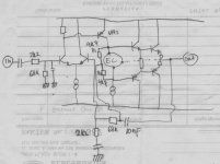
Since EC is capable of running the output stage openloop, I tried some experiment to exploit the capability of this EC output stage.
I make this. It sounds like tube (actually I don't like the term "tube sounded solid state", since we still can buy tubes (not that rare or expensive), why should imitate tubesound with solidstate? Want tube sound, well......make tube amp )
The idea is this. In global feedback power amp, the OL gain (thus the feedback) is falling towards frequency. In lower frequency there are lot of gain to be burned in feedback, but in higher frequency, the gain is not there anymore, high frequencies have less feedback than lower frequencies).
I make the DC feedback taken from VAS (via 2x4k7). But I put another 10nF from output node. I hope this way the amp will have more feedback loop only at high frequencies where naturally they are falling.
The sound is nice It has tube sound mid-low (because output stage is openloop at mid-low), but the highs are controlled well. Maybe chaotic in measurement result, but it is a nice sounding combination
Since EC is capable of running the output stage openloop, I tried some experiment to exploit the capability of this EC output stage.
I make this. It sounds like tube
(actually I don't like the term "tube sounded solid state", since we still can buy tubes (not that rare or expensive), why should imitate tubesound with solidstate? Want tube sound, well......make tube amp )The idea is this. In global feedback power amp, the OL gain (thus the feedback) is falling towards frequency. In lower frequency there are lot of gain to be burned in feedback, but in higher frequency, the gain is not there anymore, high frequencies have less feedback than lower frequencies).
I make the DC feedback taken from VAS (via 2x4k7). But I put another 10nF from output node. I hope this way the amp will have more feedback loop only at high frequencies where naturally they are falling.
The sound is nice
It has tube sound mid-low (because output stage is openloop at mid-low), but the highs are controlled well. Maybe chaotic in measurement result, but it is a nice sounding combination Attachments
lumanauw said:Mr. Cordell,
Since EC is capable of running the output stage openloop, I tried some experiment to exploit the capability of this EC output stage.
I make this. It sounds like tube
The idea is this. In global feedback power amp, the OL gain (thus the feedback) is falling towards frequency. In lower frequency there are lot of gain to be burned in feedback, but in higher frequency, the gain is not there anymore, high frequencies have less feedback than lower frequencies).
I make the DC feedback taken from VAS (via 2x4k7). But I put another 10nF from output node. I hope this way the amp will have more feedback loop only at high frequencies where naturally they are falling.
The sound is nice
This is an interesting circuit, but I'm not sure what the advantage is of depriving the output stage of the extra NFB at low frequencies.
I think the biggest reason not to make tube amps is the cost.. no the heat... no the bulk...no the tube life ...
I could make a solid state amp that sounded like a tube amp (just like Carver did years ago), but visually it would lack that warm glow.
Bob

Its an experiment, what will the sound like, if we use more feedback at higher frequencies (where naturally they are falling).This is an interesting circuit, but I'm not sure what the advantage is of depriving the output stage of the extra NFB at low frequencies.
Nixie said:Actually, orange LEDs or small neon bulbs are much closer in color.
IIRC Behringer make a small unit, I think it is a mic preamp, that actually has a (non-functioning) tube with some LEDs underneath for 'warmth'.
Why not.
Jan Didden
Hi, JCX,
In the Denon POA-6600 schematic here
http://www.eserviceinfo.com/downloadsm/23239/DENON_POA6600.html
What is IC502 doing? is it correction action (comparing output to input), but restricted to only high frequencies (because the output is via C528-C529 (0.1)?
Together with IC501, the supply is bootstrapped +/-15V towards output node. Is this +/-15V good enough (it follows output swing only by bootstrapped method)?
The download is working fine.
An externally hosted image should be here but it was not working when we last tested it.
It's inlined with an tag, not an attachment. The actual file is hosted at imageshack.us where you don't need to register to upload images.
I reduced color depth to four and changed to a PNG which works well for schematics, otherwise it was too large a file and would take long to load.
I reduced color depth to four and changed to a PNG which works well for schematics, otherwise it was too large a file and would take long to load.
that's some schematic, thanks Nixie
at a quick scan it looks to me like the op amps are powered with a floating supply that has low Z comon mode drive from TR507,8 = the unity gain buffer of the descrete input stage, but clearly there has to be some other bootstrapping going on to get +15.2/-15 V supplied op amps to drive a Darlington tripple with +/-80 V supplies
hopefully there is a theory of operation section, maybe I can download later or from another machine (or someone could email the file to me...)
as mono blocks it is possible that the +/-80 V output supply is floating and that the output stage is actually CE mode with the emitters at signal/power ground
- Home
- Amplifiers
- Solid State
- Bob Cordell Interview: Error Correction