...comparing to others in a series of blind tests!Originally posted by traderbam
...and listen to it. 😉
I shouldn't be hard to construct an automated switchbox to interface to an ABC/hidden reference program. There's already one for comparing codecs here; the code changes for driving switchboxes instead should be minor.
traderbam said:The THD test is not a sufficiently reliable measure of accuracy, in my experience.
Nobody says it is. Bob went so far as to design specific pieces of test equipment to nail down the linearity of his designs. All the available liturature (and no, I am NOT going to provide a comprehensive reference list) convinces me that those tests far outmeasure any listening tests.
Jan Didden
gootee said:
...still temporarily available, at http://www.fullnet.com/u/tomg/EC_Amp.asc. To actually run it, you would also need http://www.fullnet.com/u/tomg/OPA541E.SUB . Note that the downloadable version is the slightly-older one, without the magic notch filter.
thanh said:@gootee: I downloaded your schematic, file .asc 17KB. I open it by LTSpice but there is nothing
While I was out of town, my ISP had a hard disk crash, making my webpage area temporarily unavailable. They should be there again, now. Sorry for the inconvenience.
- Tom Gootee
http://www.fullnet.com/u/tomg
Bob Cordell said:
No. First you have to build a real amplifier and measure it.
Bob
Ah, thank you for reminding me to that! 😉 I did my last audio design back in 1983, then I changed to industrial (amp) design....
there counts only the specs ,the price and the delivery time!
But...who knows, come back the times I like to bother me with golden ears!

Heinz!
Attachments
Jan,
Bob wrote in reply to John Curl:
I wrote:
Bob replied:
THD mesaurements on valve amps are usually relatively poor too. So go figure. I have.
Brian
PS: Maybe this topic should be in another thread.
Bob wrote in reply to John Curl:
This audio business is very subjective, and there is a lot that we still don't know. I have absolutely no problem with you preferring the sound of a design without negative feedback, or a design with wide open-loop bandwidth. It is possible that such a design is better and we just don't yet know why. I call that the "X" factor, and am comfortable with that. I don't know why my 35 wpc KT88 tube amp sounds so damn good, but I don't lose sleep over it.
I wrote:
Did you measure it's phase modulation?
Bob replied:
No, I didn't measure its PIM, but I probably should 🙂. I didn't measure its TIM using the DIM-30 or DIM-100 test, either. However, I'd bet that it would show moderate amounts of both. Go figure.
THD mesaurements on valve amps are usually relatively poor too. So go figure. I have.
Brian
PS: Maybe this topic should be in another thread.
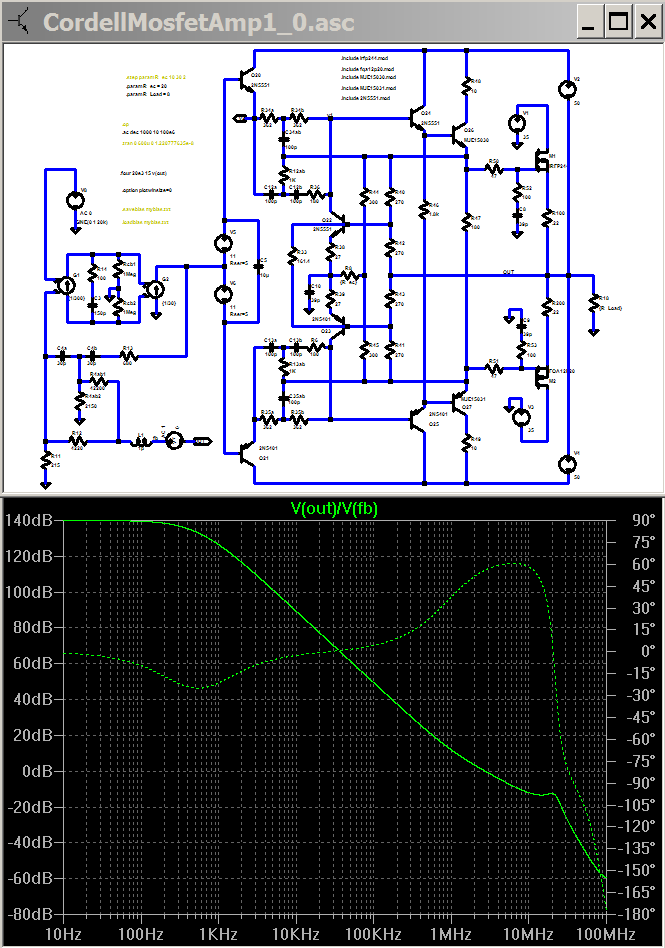
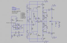
Here I’ve added local positive feedback to extend both the error correction amplification bandwidth and to take advantage of more open loop gain from the front end, the “minor” structural changes include reconnecting Q24,5 collectors to add current gain, and bootstrapping the supply to the error correction/driver stage
I see 0.5 ppm thd from the sim – 8X “better” than the nominal error correction circuit above
The price paid is the loss of phase margin,
The ac plot shows gain intercept at 2.7 MHz, 56 degrees
This is not necessarily the best approach – but may answer the question of whether positive feedback can improve distortion performance
My view is that the AC positive feedback bootstrapping of the error correction gain RC networks has extended the bandwidth of the local ec loop and increased the input impedance of the whole ec/output stage at higher frequencies
With increased input impedance at higher frequencies it is then attractive to split/bootstrap the front end diff/vas compensation cap C4, moving the sim’s 20KHz outer loop gain from ~45 dB to ~75 dB, this increased outer loop gain is partially offset by the reduction of the error correction loop gain due the increased drive impedance, but the net is a reduction in simed distortion
Attachments
EC implemented - Academia measurements
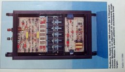
OK guys, now that we've started talking measurements here are the measurements of a real world error correction output stage, a.k.a. Academia.
Before I give you the results, I wish to say that the measurements were done in a home environment, on a real world loudspeaker with a nominal impedance of 8 ohm and using my home measurement set. Also, you will note a peak in the frequency response at 50kHz, which is due to the interstage transformers I mentioned earlier (compensation required). Given the circumastances, I think the measurements are very good but will appreciate any comments and suggestions.
Legend:
THD + N = no filters
K2 = second harmonic
K3 = third harmonic
Measurement set = Neutrik Analyzer 337
Regards,
Milan
Attachments

traderbam said:Jan,
Bob wrote in reply to John Curl:
I wrote:
Bob replied:
THD mesaurements on valve amps are usually relatively poor too. So go figure. I have.
Brian
PS: Maybe this topic should be in another thread.
Brian, these are valid points, but in this thread we discuss design linearity issues, not listener preferences. There may or may not be a correlation between the two. So, therefore, listener preferences are not a good indicator for design linearity if at all.
So, I agree, lets leave this out of this thread, there are other threads for this.
Jan Didden
Hi John,
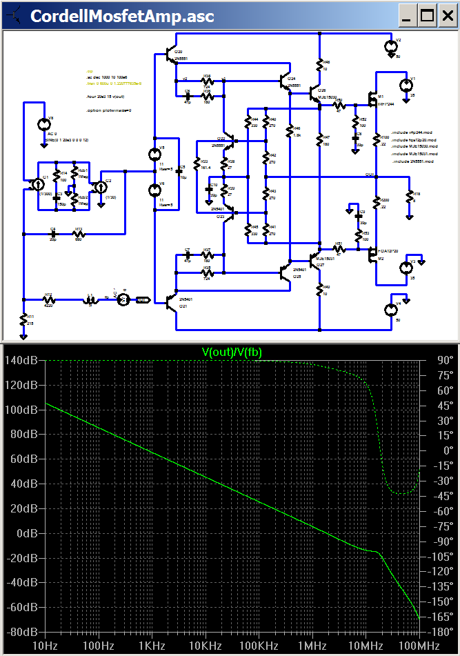
I'm not sure I'm reading your graphs properly but it looks like the second circuit is somewhat unstable? I've attached my current LTSpice model of Bob's output stage so you can see the resistor values he has actually used. You should see the "EC" loop gain is about 31dB flat to a knee at some 90kHz or so with unity gain at about 3.4MHz. This is into an 8-ohm resistor. The circuit to thr right is nothing to do with it...just my FET "matching" jig.
Brian
I'll publish this again once I've got better transistor matches in it, along with loop gain graphs.
Attachments
Milan,
This looks pretty exciting. Can you measure the THD 20 like Bob did on his and give the result? I'm not sure what load Bob used - I guess an 8-ohm resistor.
Have you got a means to measure frequency and phase repsonse?
Brian
This looks pretty exciting. Can you measure the THD 20 like Bob did on his and give the result? I'm not sure what load Bob used - I guess an 8-ohm resistor.
Have you got a means to measure frequency and phase repsonse?
Brian
Hi Brian:
The measurement printout shows the frequency response up to 40kHz and THD up to 40kHz. The only caveat is that the frequency response of the Analyzer's own measurement amplifier affects negatively THD measurement results at frequencies above 20kHz. If you take a look at the printout, you'll se that K2 and K3 are approx. 0.05%. As with the frequency response, one should bear in mind that the THD measurement results are inclusive of interstage transformer characteristics.
Regards,
Milan
Milan,
Let me do a "back of a fag packet" estimate. Bear in mind I don't smoke. If both k1 and k2 are 0.05% I make the distortion -60dB or higher. That seems reasonable to me. What resistor values are you using...the ones in Bob's 1984 paper or the actuals he told me earlier in this thread?
Brian
Let me do a "back of a fag packet" estimate. Bear in mind I don't smoke. If both k1 and k2 are 0.05% I make the distortion -60dB or higher. That seems reasonable to me. What resistor values are you using...the ones in Bob's 1984 paper or the actuals he told me earlier in this thread?
Brian
Hi Brian:
I used the exact same circuit that Bob published in 1984. My resistors values are taken from the original paper (1% tolerance). I haven't done any adjustments to the circuit and I'm not sure I'm going to since I happen to be quite satisfied with the things as they are now. I'm sure the measurements would have been even better had they been performed in a lab environment and using an 8-ohm resistor load.
Regards,
Milan
Milan,
With those resistor values simulation estimates you are applying 23dB of feedback. If you disconnect the outer loop of the EC (the connection between output and the junction of R42 and R43) the distortion ought to rise to about -37dB or 1.4% (0.7% K1 and K2) if all these estimates are right.
Brian
With those resistor values simulation estimates you are applying 23dB of feedback. If you disconnect the outer loop of the EC (the connection between output and the junction of R42 and R43) the distortion ought to rise to about -37dB or 1.4% (0.7% K1 and K2) if all these estimates are right.
Brian
In a nutshell, Brian, you now want me to butcher up a perfectly good output stage because your simulator doesn't work properly?  I'll see what I can do...😀
Regards,
Milan
P.S. It may take me a while.
I'll see what I can do...😀 Regards,
Milan
P.S. It may take me a while.
Milan wrote:
 😀
😀
PS: Whatever you do, don't disconnect R42 from R43 or you'll need a bucket of sand.
Hey, you asked for it!My soldering iron's hot and ready. I have about 10 kilos of transistors lying about. All systems go!
😀PS: Whatever you do, don't disconnect R42 from R43 or you'll need a bucket of sand.
traderbam said:The THD test is not a sufficiently reliable measure of accuracy, in my experience.
THD-20 is a very good test, but it is not a complete test, for shure. I usually prefer 19 + 20 kHz twin tone with full spectral analysis for high frequency non linearity. And, of course, there is no substitute for a decent listening test.
That having been said, please elaborate on your experience with THD not having been a reliable measure of accuracy.
Bob
- Home
- Amplifiers
- Solid State
- Bob Cordell Interview: Error Correction