Pavel's amplifier
I reviewed the schematic of Pavel's amplifier, and I agree with Darkfenriz that his output stage is a near-exact copy of the design I published in HAES in 1984. Even some of the resistor values are unchanged. Too bad he compromized the design by using un-degenerated bipolar differential inputs pairs with old-fashioned Miller compensation rather than just copying the whole design") .
.
Cheers,
Bob
I reviewed the schematic of Pavel's amplifier, and I agree with Darkfenriz that his output stage is a near-exact copy of the design I published in HAES in 1984. Even some of the resistor values are unchanged. Too bad he compromized the design by using un-degenerated bipolar differential inputs pairs with old-fashioned Miller compensation rather than just copying the whole design
.Cheers,
Bob
Hi, Mike,
Maybe the RF is small, but what about anything >20khz (up to Mhz, like radiation of SMPS) electromagnetic field, wouldn't they be captured by speaker cables?
If the closed loop feedback system is only processing audio signal then it will be optimal. But if the system is also processing other things that is not related to the audio signal, wouldn't it make intermodulation? Like NP said, a transistor is blind. It will process anything that appears on it's base/gate without knowing whether a certain signal is audio or "junk".
lumanauw said:Hi, Mike,
Maybe the RF is small, but what about anything >20khz (up to Mhz, like radiation of SMPS) electromagnetic field, wouldn't they be captured by speaker cables?
That was my point. The conditions are not there for such a fragile signal to be coupled via the speaker cables into any of the gain stages.
Regards, Mike.
lumanauw said:Hi, Bob Cordell,
I've got a question about your amp that I'm still not clear. In post #7. What is the reason behind the connection of Q7-Q8 is not connected to output node (like Q5-Q6 and Q9-Q10)?
For sharper coloration on highs, I suppose?
connection of Q7, Q8
Lumanauw,
Directly connecting the emitters of Q7 and Q8 together through R11 keeps driver transistors always on, rather than allowing them to be cut off when their associated output transistor is also turned off. This is a variant of the Locanthi "T" output stage. Transistors Q5 and Q6 could have also been connected this way, but since they are smaller, higher-speed devices, it would have made less of a difference. Note that this schematic was only put in the article as an example of a typical simplified complementary bipolar amplifier of the time for discussion purposes, and was not intended to represent a particularly high quality design.
Bob
Ultima Thule said:Mike Bettinger,
do you have any hands on experiences of EMI and audio amplifiers, any experiment of your own you could tell us about?
Cheers Michael
I have 30 years hands on experience with this subject and my day job is designing sensors systems for monitoring process conditions in a noisy electrical environment. Semiconductor fabrication.
Regards, Mike.
In my opinion, the biggest source of EMI today are GSM phones and wi-fi networks, rather than nearby AM or FM commercial transmitters. A while back, I had quite some trouble to bring the effect of GSM phones on the mikes and broadcast consoles (HF traps, etc.) at the place where I work down to acceptable levels. GSM phones transmit at very high powers, particularly when searching for network signals or attempting to establish a connection, so systems such as dynamic microphones are virtually impossible to protect from that kind of thing. Dynamic microphones and small multimedia speakers act like excellent little antennas for the reception of the repetition frequencies of data packages. As a result, in our efforts to minimize the intrusion of GSM interferences, we no longer use dynamic mikes, only condenser ones.
On the other hand, I’ve heard some acquaintances of mine talk about very audible effect of wi-fi networks on the sound reproduced by their home audio systems. As I haven’t had any similar experiences myself, I can’t either confirm or deny these allegations but I’m guessing that any negative effects of wi-fi networks on home audio systems will be tracked to interconnects, rather than amplifier output.
So, although the amplifier-speaker connection has a very low impedance at audio frequencies, at higher frequencies it becomes a system with distributed parameters, where certain parts of the system can act as isolated reception antennas. Personally, I don’t believe that the attenuation of the signal from the amplifier’s output (with NFB) to the inverting input (loop gain) at audio frequencies works well for high frequencies too. Now, I’m sure that anyone out there who has ever had the misfortune of witnessing the sound of an amplifier-turned-oscillator needs no ghastly reminder from me of what a HF signal can do to an amplifier.
Regards,
Milan
Re: RFI Ingress
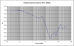
I do, and I also do measure RFI signal throughput in preamps and power amps.
Pavel Macura
Bob Cordell said:I've often wondered about RFI ingress into the guts of an amplifier via the antenna effect of the speaker cable, and I do take measures in my designs to mitigate it. I must honestly say, however, that I have never tried to measure it.
I do, and I also do measure RFI signal throughput in preamps and power amps.
Pavel Macura
Attachments
Re: Pavel's amplifier
Oh no, it was an old design linked here. For years he has used input JFETs and MOSFETs (DPA380SSE, DPA386SSE, DPA388SSE).
Regards,
Pavel Macura
Bob Cordell said:I reviewed the schematic of Pavel's amplifier, and I agree with Darkfenriz that his output stage is a near-exact copy of the design I published in HAES in 1984. Even some of the resistor values are unchanged. Too bad he compromized the design by using un-degenerated bipolar differential inputs pairs with old-fashioned Miller compensation rather than just copying the whole design
Cheers,
Bob
Oh no, it was an old design linked here. For years he has used input JFETs and MOSFETs (DPA380SSE, DPA386SSE, DPA388SSE).
Regards,
Pavel Macura
Re: Re: RFI Ingress
I don't measure, but I always think how good is output as a rectifier on high frequencies. However, if it is a pair of naked emitters already biased so they are ready to rectify even small signals try to imagine couple of diodes that rectify and feed input of the amp with rectified signal... Now imagine this signal amplified and it modulates rectification changing bias of diodes...
PMA said:
I do, and I also do measure RFI signal throughput in preamps and power amps.
Pavel Macura
I don't measure, but I always think how good is output as a rectifier on high frequencies. However, if it is a pair of naked emitters already biased so they are ready to rectify even small signals try to imagine couple of diodes that rectify and feed input of the amp with rectified signal... Now imagine this signal amplified and it modulates rectification changing bias of diodes...
My three gurus
Dear Bob,
you was one of my three Gods - Borbelly, Hawksford and you... When I saw your schematic and explanation, I was quite whole-hearted...But I was living beside iron curtain and here wasn't vertical mosfets at that times, so I had try it with old Hitachi's...But with these devices amp wasn't stabil so I was searching some other alternative of input and VAS. As you can see, it is Borbelly's front end, which gave me at the end very credit results - traces on scope was quite the same like on your pics. Later I had try some other connections, but at the end I was turn back again to Erno's child ( only with little modification ). Your basic circuit I'm using continually to this time and I¨m very satisfied.
Your sincere fan,
Pavel Dudek
PMA said:
My 2 cents: 2 Zeners needed (and 1 resistor on input, or 2 resistors in collectors of input transistors) to protect output FET gates in case of overload by output current. Input transistors will kill'em if power voltage is enough.
PMA said:
and mine, #3995228
Attachments
Mine, public domain (no commercial usage without my permission)

Error on schematics: left resistor with 2 pots are connected to the ground.
It is symmetrical operational amplifier with 100% NFB. Maximum output current is limited by resistors in tails. Complex tails are made for lower idle currents. One half of differential amplifiers is represented by diodes instead of emitter followers since output resistance is low, and diodes have much bigger break-down voltage than BE junctions.
- Home
- Amplifiers
- Solid State
- Bob Cordell Interview: Error Correction