Hi Jan,
Small correction, with Hec the loop gain is only 1.
Hans
Hans, it is the positive feedback loop that creates the very high loop gain, even if all the separate blocks do not need to have high gain.
Using positive feedback to increase loop gain, so that you can then successfully apply negative feedback to improve performance has been used with tube amps in particular right after WWII.
Jan
Bob,
First of all, the last thing I had in mind was to criticize your excellent Amp design.
You used a proven error correction mechanism and executed it perfectly.
What I was trying to say is that from a practical point of view, AEF is to be preferred over HEC, because you need no tuning.
To say that 3% resistors are o.k. means that you first have to find the 0% point.
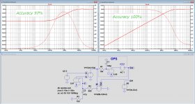
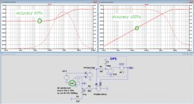
Using 3% resistors means a 30dB error correction over the audio range, see left image below.
THD20 could theoretically even be reduced by 45dB when having used a 0.3% resistors, see second image at the right for 0% resistors.
When using AEF, you will theoretically get the distortion reduction as in the image at the right without any trimming at all going down all the way down, ending at the OL gain of the amplifying path used.
Hans
.
First of all, the last thing I had in mind was to criticize your excellent Amp design.
You used a proven error correction mechanism and executed it perfectly.
What I was trying to say is that from a practical point of view, AEF is to be preferred over HEC, because you need no tuning.
To say that 3% resistors are o.k. means that you first have to find the 0% point.
Using 3% resistors means a 30dB error correction over the audio range, see left image below.
THD20 could theoretically even be reduced by 45dB when having used a 0.3% resistors, see second image at the right for 0% resistors.
When using AEF, you will theoretically get the distortion reduction as in the image at the right without any trimming at all going down all the way down, ending at the OL gain of the amplifying path used.
Hans
.
Attachments
Hans, it is the positive feedback loop that creates the very high loop gain, even if all the separate blocks do not need to have high gain.
Using positive feedback to increase loop gain, so that you can then successfully apply negative feedback to improve performance has been used with tube amps in particular right after WWII.
Jan
Jan,
We can agree to disagree, see my posting one step back.
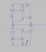
As you see in the circuit diagram, there is no gain involved.
As I said earlier, this was the geniality of Hawksford's invention, that with a gain of exactly 1 you could get a perfect error cancellation.
Hans
I see positive feedback in that diagram, which means a lot of gain. That gain is 'cancelled' by 100% negative feedback. Get the feedback not exactly right, and the gain pops up again, either positive or negative! Yes we agree to disagree.
BTW Your results in the previous post exactly match mine. At the time, I spend a lot of time learning MathCad to calculate those curves, and they came out exactly the same as the ones you show above!
Wish we could get done with that Corona stuff and visit each other again in the flesh ....
Jan
BTW Your results in the previous post exactly match mine. At the time, I spend a lot of time learning MathCad to calculate those curves, and they came out exactly the same as the ones you show above!
Wish we could get done with that Corona stuff and visit each other again in the flesh ....
Jan
Bob,
First of all, the last thing I had in mind was to criticize your excellent Amp design.
You used a proven error correction mechanism and executed it perfectly.
What I was trying to say is that from a practical point of view, AEF is to be preferred over HEC, because you need no tuning.
To say that 3% resistors are o.k. means that you first have to find the 0% point.
Using 3% resistors means a 30dB error correction over the audio range, see left image below.
THD20 could theoretically even be reduced by 45dB when having used a 0.3% resistors, see second image at the right for 0% resistors.
When using AEF, you will theoretically get the distortion reduction as in the image at the right without any trimming at all going down all the way down, ending at the OL gain of the amplifying path used.
Hans
.
Hi Hans,
No problem. We can agree to disagree on which technique is the better one. I have no experience building the AEF design, I just know that the HEC design I did worked extremely well, and that the 30-dB distortion reduction I got was impressive enough for me (this, of course, is at 20 kHz, which is where the rubber really meets the road).
Have you built and measured an AEF design?
One thing further I should add about my implementation of HEC is that to make best use of it, one should use boosted rails for the IPS, VAS and drivers, since the HEC circuit consumes some voltage headroom. I believe that the need for boosted rails to make the best of HEC is the biggest factor in increasing the cost of an amplifier equipped with HEC. Adding a couple of transistors and resistors is in the noise.
Having said that, even ordinary amplifiers often perform better with the greater front-end headroom provided by boosted rails.
In my experience, trimming the pot was very easy and pretty much rock solid. BTW, I forgot to mention that the pot can be trimmed when the output stage is operating open loop, so the distortion null is much easier to see with ordinary test equipment. I usually build every amplifier with the option of closing the loop ahead of the output stage. This just takes a 3-pin header wherein 2 of the pins are shorted with a header jumper that can easily be moved.
Cheers,
Bob
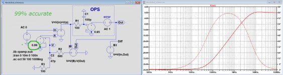
Jan, here you are with 1% resistors.
Hans
.
Nice. As expected. I love it when it all comes together ;-)
Jan
Hi Bob,Hi Hans,
Have you built and measured an AEF design?
Cheers,
Bob
Yes, that is what I have shown here to you.
Bob Cordell Interview: Error Correction
Hans
Hi Hans,
I'm sorry I missed that. Those are very good measurements, and the agreement is impressive. Can you post the design or has it been posted before?
As you probably know, I like 19+20 kHz CCIF IM measurements, in large oart because the distortion components are in-band and a wideband spectrum analyzer is not needed. However I did not publish those measurements for the MOSFET power amplifier (I actually may not have done them back then). CCIF numbers are usually smaller than THD+N at 20 kHz. Do you have THD-20 measurements for that amp?
Cheers,
Bob
Hi Hans,Coming in very, very late, I just wondered whether Edmond has finished his amp to compare it against the Cordell solution.
[snip]
Hans
No, I have never built this "AEF" amp. The only reason I simmed this amp is to shed another light on HEC and to "prove" that HEC is equivalent to an output stage with a large amount of negative feedback.
To all,
One can find the schematic here and a slightly improved version here.
Hi Bob,Hi Hans,
This is a very good question, and I wish Edmond was still on DIYaudio.
[snip]
Cheers,
Bob
Don't worry. As you can see, I'm still alive.
Cheers, E.
Exactly!Hi ! Nice to meet again Bob, Jan !! Well over 10 years later !
Yes, after some dedication to the error correction concept, I fell to the conclusion it is an extreme form of negative feedback where essentially you have an inner node with infinite gain attained through unity gain positive feedback loop. This infinite gain in the global feedback loop makes for ideal correction.
[snip]
Cheers !!
Cheers, E.
Hi Hans,
No, I have never built this "AEF" amp. The only reason I simmed this amp is to shed another light on HEC and to "prove" that HEC is equivalent to an output stage with a large amount of negative feedback.
To all,
One can find the schematic here and a slightly improved version here.
Hi Bob,
Don't worry. As you can see, I'm still alive.
Cheers, E.
Hi Edmond,
It is great to have you back!
Cheers,
Bob
Hi Hans,
Do you have THD-20 measurements for that amp?
Cheers,
Bob
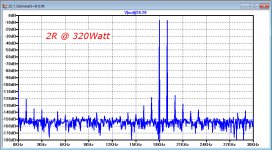
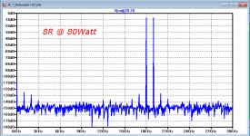
THD-20 figures without AEF are:
For 8R load
0.035% at 80Watt
0.040% at 100Watt
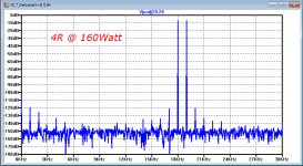
For 4R load
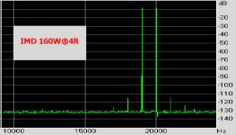
0.41% for 160Watt
0.46% for 200Watt
I had to use the existing bipolar 3 EF endstage of my ML20.6, but the IMD figure at 160Warr@4R below shows the effectiveness of the AEF.
Hans
.
Attachments
Exactly!
Cheers, E.
So you dont set up error correction after the rolloff.
Like an output driver set up with gain of 2?
Attachments
THD-20 figures without AEF are:
For 8R load
0.035% at 80Watt
0.040% at 100Watt
For 4R load
0.41% for 160Watt
0.46% for 200Watt
I had to use the existing bipolar 3 EF endstage of my ML20.6, but the IMD figure at 160Warr@4R below shows the effectiveness of the AEF.
Hans
.
What’s the 1 kHz level in your picture ?
How works DENON's Error Correction from the Models PMA900V and PMA700V ?
check out post #22 under
about the Denon PMA-700 amp.
The mentioned attachments I had also upload here
check out post #22 under
about the Denon PMA-700 amp.
The mentioned attachments I had also upload here
Attachments
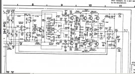
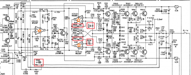
I couldn't understand this DENON's error correction circuit but currently in my understanding, it is detecting voltage drop of the output stage by the gain of 2 differential amplifiers and adding them from R531 4.3kΩ and R545 + R515//R513//R511//R517 ≒2.2kΩ which forms about 1/2 of gain , thus combing opamp stage,
gain of 1 is achieved. In fact it have PFB through R547 but I could not understand the operation.
From understanding the HEC is PFB+NFB, why does Denon have two feedback amplifiers? It may be better to be classified non switching circuit combined with D511-D517, rather than error correction.
I think the schematic has errors or a revision around IC511, it must use dedicated opamps for each channel.
The opamp basically a typical feedback gain of unity, with the feed-forward path from +input to supply pin, which is the reference node of 2nd stage of the opamp circuit. (miller compensation stage) Unity gain feedback plus feed-forward to supply pin have multiple benefits that are
more linear input stage because it doesn't need to charge miller comp cap why 2nd stage is on floating at almost equal voltage to the output voltage.
input stage has fixed VCE like bootstrapped-cascode.
greater bandwidth by bypassing the input stage.
The bandwidth may help multiple feedback amplifier -AEF type circuits in the thread.
The circuit topology hans posted have a feed-forward path but it does not always exist in multiple feedback circuits.
Bob Cordell Interview: Error Correction
- Home
- Amplifiers
- Solid State
- Bob Cordell Interview: Error Correction