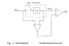
Another error-corrected circuit
It was published in December issue of Russian magazine "Radio" in 2005 by Michael Kulish. I have got that article in DJVU format however it is in Russian") . I've just posted in another thread results of a simulation of one of the circuits described in that article and than thought about posting it here. I hope I would not be punished for a little cross-posting as it seems appropriate. If it is not, I apologise.
. I've just posted in another thread results of a simulation of one of the circuits described in that article and than thought about posting it here. I hope I would not be punished for a little cross-posting as it seems appropriate. If it is not, I apologise.
I know that the author of this idea is member of DiyAudio, however I can not find him at the moment as I forgot his nickname at the forum .
Here it goes:
Cheers
Alex
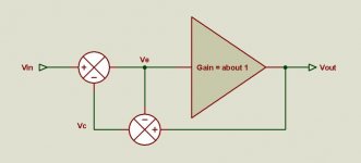
P.S. - there is no feedback in this circuit except local... correction is done by summing two currents and in the article the author describes a full-blown and fully symmetrical VAS with this kind of correction.
P.P.S - the FFT graphs are for 1 V RMS output at 10 kHz, the gain is about 9 dB
It was published in December issue of Russian magazine "Radio" in 2005 by Michael Kulish. I have got that article in DJVU format however it is in Russian
. I've just posted in another thread results of a simulation of one of the circuits described in that article and than thought about posting it here. I hope I would not be punished for a little cross-posting as it seems appropriate. If it is not, I apologise.I know that the author of this idea is member of DiyAudio, however I can not find him at the moment as I forgot his nickname at the forum
. Here it goes:
Cheers
Alex
P.S. - there is no feedback in this circuit except local... correction is done by summing two currents and in the article the author describes a full-blown and fully symmetrical VAS with this kind of correction.
P.P.S - the FFT graphs are for 1 V RMS output at 10 kHz, the gain is about 9 dB
Attachments
Bob Cordell said:Hi Edmond,
I think that both ways of looking at EC are valid and necessary, as each has its value in exposing the behavior of the approach.
Even if it is viewed as nothing more than a negative feedback loop inside of which we put a unity gain positive feedback loop to get theoretically infinite forward gain, the technique is extremely effective and no more difficult to compensate than an ordinary feedback loop, if you know what you are doing, notwithstanding Charles' assertion that stability is a problem.
Part of its advantage comes from the fact that it is an extremely tight, fast feedback loop (or whatever) around the output stage.
By the way, the best reference to my error correction work is the JAES paper that is available as a pdf on my web page at www.cordellaudio.com under "published papers."
Cheers,
Bob
Hi Bob,
Thank you for the hint. Indeed, the JAES paper is much more informative than the publication in the Siliconix handbook.
Cheers, Edmond.
I scanned Jerry Graeme's article on generilized feedback models on my home page. It's faily large (6.5MB) so will take a few secs to download.
Using Graeme's method, the effective feedback factor of the ec output stage I posted above comes to 1/A-1, with an 'A' that is *about* 1. It's easy to see that if A would be exactly 1, (no distortion, no errors) there would effectively be no feedback at all. The farther A departs from the ideal '1', the more feedback we get, but only to the amount of the error, the difference between the actual 'A' and '1'. There is no main signal feedback, if you know what I mean.
If 'A' becomes more than '1', the feedback becomes negative as to reduce the closed loop gain. If 'A' becomes too small (smaller than '1'), the feedback becomes positive as to increase the cl gain to '1'. In each case, just the right amount is added/subtracted to the input signal to compensate for the loss or excess of A.
Now, where's this 'infinite gain' thing?
Isn't this a great little circuit
Jan Didden
janneman said:[snip]
Using Graeme's method, the effective feedback factor of the ec output stage I posted above comes to 1/A-1, with an 'A' that is *about* 1. It's easy to see that if A would be exactly 1, (no distortion, no errors) there would effectively be no feedback at all. The farther A departs from the ideal '1', the more feedback we get, but only to the amount of the error, the difference between the actual 'A' and '1'. There is no main signal feedback, if you know what I mean.
If 'A' becomes more than '1', the feedback becomes negative as to reduce the closed loop gain. If 'A' becomes too small (smaller than '1'), the feedback becomes positive as to increase the cl gain to '1'. In each case, just the right amount is added/subtracted to the input signal to compensate for the loss or excess of A.
Now, where's this 'infinite gain' thing?
Isn't this a great little circuit
Jan Didden
Hi Jan,
What you are telling us looks very promising. I suppose you are referring to your pax-b.pdf schematic. right?
As soon as I have more time I'll have close look at it and poke around with a (simulated) gain probe.
Cheers, Edmond.
lumanauw said:Hi, Janneman,
How is the behavior of an amp with EC in clipping condition? Will the EC makes the amp clips harder (than if there is no EC), because EC will try to meet the targetted point (and it cannot be met due to rail limitation)?
Hi David,
I haven't tested it rigourously yet, but what I see on the scope seems more or less what I would expect in a feedback amp. I have the *impression* it isn't much different.
I am currently looking at putting reverse-parallel diodes across the input resistor (the one that effects the EC) so that when overdriven, the EC cannot grow higher. Problem here is that it starts to influence the THD behaviour already before overdrive.
Jan Didden
Is it the same mechanism with the current sensing (accross RE) that is used for current limiting of outputstage that in the end affects the sonics?I am currently looking at putting reverse-parallel diodes across the input resistor (the one that effects the EC) so that when overdriven, the EC cannot grow higher. Problem here is that it starts to influence the THD behaviour already before overdrive.
janneman said:
Hi David,
I haven't tested it rigourously yet, but what I see on the scope seems more or less what I would expect in a feedback amp. I have the *impression* it isn't much different.
I am currently looking at putting reverse-parallel diodes across the input resistor (the one that effects the EC) so that when overdriven, the EC cannot grow higher. Problem here is that it starts to influence the THD behaviour already before overdrive.
Jan Didden
I think the main thing is to just keep all devices out of saturation when clipping happens. It is also nice if they also don't swing much further than they need to, so delay time coming back is kept short.
Bob
lumanauw said:
Is it the same mechanism with the current sensing (accross RE) that is used for current limiting of outputstage that in the end affects the sonics?
In a sense it is. The issue with most VI-sensing protection systems is that you would want them to be inactive and then turn on at the exact point of overload. But a single transistor doesn't work like a switch when sensing Ic (+ Vce), so before the overload point it already starts, slowly, to steal current from the drivers, thus increasing distortion.
You can add circuit complexity to make it switch more abrubtly, but that means generally more gain in the protection loop and oscillations around the protection point. You can add hysteresis to avoid that, which again adds circuit complexity.
Jan Didden
EC loop gain
I thought this IS Bob's EC thread, isn't it?
Hi Jan,
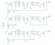
I have taken your advice to look at a complete circuit, that is, combined with negative feedback. Lacking a complete schematic of your design, I have made my own, although very basic: an input stage, VAS, unity gain buffer, EC unit and output stage. There are three versions of them, each with the loop broken at a different place.
See my next post for the gain-frequency response and further comments.
janneman said:Hi Edmond,
[snip]
Moderators: please can you split these posts to Bob's EC thread?
Jan Didden
I thought this IS Bob's EC thread, isn't it?janneman said:[snip]
You can't take a system with combined pos and neg feedback, delete one of the two and then say: see, it's extra loop gain! or another statement.
Hi Jan,
I have taken your advice to look at a complete circuit, that is, combined with negative feedback. Lacking a complete schematic of your design, I have made my own, although very basic: an input stage, VAS, unity gain buffer, EC unit and output stage. There are three versions of them, each with the loop broken at a different place.
See my next post for the gain-frequency response and further comments.
Attachments
EC loop gain
(continuation from previous post)
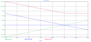
The first one (green curve ) is just the loop gain of the EC circuit. At moderate frequencies the gain is very low, apparently, because all the "work" is done by the neg. FB loop. At around 10MHz, a frequency at which local instabilities might raise its head, the loop gain is much higher and implies that the EC circuit should have good HF properties.
The second one (blue curve) shows the global FB gain seen at the inverting input. Nothing special about it and (almost) the same without EC.
The third one (red curve) reveals a totally different behavior, an enormous loop gain, getting infinite if the gain of the EC stage itself set to exactly one (can't show this as my simulator makes objections)
So here is "this 'infinite gain' thing"
Cheers, Edmond.
janneman said:[snip]
Now, where's this 'infinite gain' thing?
(continuation from previous post)
The first one (green curve ) is just the loop gain of the EC circuit. At moderate frequencies the gain is very low, apparently, because all the "work" is done by the neg. FB loop. At around 10MHz, a frequency at which local instabilities might raise its head, the loop gain is much higher and implies that the EC circuit should have good HF properties.
The second one (blue curve) shows the global FB gain seen at the inverting input. Nothing special about it and (almost) the same without EC.
The third one (red curve) reveals a totally different behavior, an enormous loop gain, getting infinite if the gain of the EC stage itself set to exactly one (can't show this as my simulator makes objections)
So here is "this 'infinite gain' thing"
Cheers, Edmond.
Attachments
Wow! Need to look at that.
A couple of questions first: what is the open loop gain of your circuits? I'm not very familiar with your particular implementation so this would help.
The (implicit) assumption in my circuit is that the open loop gain should be *about* the same as the required cl gain. If the ol gain is (much) higher, the circuit will tend to 100% feedback around the (very) high ol gain so that might be seen as a 'huge' loop gain. What you would see in such a case is just the ol gain. Since there would then be a quite large delta between ol and cl gain, of course that shows up as loop gain.
One of the nice things of ec is that you don't need large ol gain....
The RED curve is from fig 3/ output 3?
Jan Didden
janneman said:Wow! Need to look at that.
A couple of questions first: what is the open loop gain of your circuits?
Hi Jan,
I suppose you mean the gain at the non-inverting input with enabled EC and disabled global NFB (R6 disconnected in fig. 2).
Well very simple, generally, the gain of the NFB loop multiplied by 31 ( (R5+R6)/R6 ). So, about 70db at 10kHz.
janneman said:I'm not very familiar with your particular implementation so this would help.
Apparently you are not familiar with the typical MicroCap symbols, but this very basic implementation covers most of the specific implementations, including yours, although I have no knowledge about your front-end, and including Bob Cordell's version, except the frequency compensation by means of C2.
janneman said:The (implicit) assumption in my circuit is that the open loop gain should be *about* the same as the required cl gain. If the ol gain is (much) higher, the circuit will tend to 100% feedback around the (very) high ol gain so that might be seen as a 'huge' loop gain. What you would see in such a case is just the ol gain. Since there would then be a quite large delta between ol and cl gain, of course that shows up as loop gain.
Now I'm getting confused. In first instance you were telling me that I should also take into account the effect of NFB, which only makes sense in case of a consideral amount of NFB. Now you are advocating a low amount of NFB.
Anyhow I have showed you that EC increases the gain of the FB loop enormous, with no NFB in my previous post and with a fairly large amount of NFB as shown here.
That depends on your requirements.janneman said:One of the nice things of ec is that you don't need large ol gain....
janneman said:The RED curve is from fig 3/ output 3?
Jan Didden
Look at OUT3.
Cheers, Edmond.
estuart said:
Hi Jan,
I'm sorry to say, but I agree with Charles. Theoretically, EC is nothing else than reducing the distortion to zero by means of a FB circuit with infinite gain. If you don't believe me, just break the loop from output to the node of R42 and R43 in Bob's example. You'll see a loop gain in the order of 40 to 50 dB. So, Charles isn't wrong, it is just a different point of view.
Cheers, Edmond.
Edmond, would you make this claim of infinite gain based on Figure 11 in Bob's paper?
Pete B.
PB2 said:Edmond, would you make this claim of infinite gain based on Figure 11 in Bob's paper?
Pete B.
Hi Pete,
No, figure 12. BTW, I wouldn't call it a claim, rather an observation.
Cheers, Edmond.
OK Edmond, I may have been confusing things unnecessary. Apologies.
I have always said that in my implementation, there is NO ol gain in excess of the closed loop gain. Go ahead, read that again.
In cas of my ec power amp, I have published the circuit in the attachment. You will see that the ol gain A = 'about 1'. Then there is the ec 'feedback' to the input summer. What I would think is that 'opening the loop' would be to break that connection from the ec summer to the input summer. In THAT situation, is there 'infinite' loop gain???
In this circuit the feedback factor is (1/A)-1 as noted before. If A is too large (A>1), the feedback becomes nfb to bring the gain down to 1. If A is too small (A<1), the feedback becomes pos to increase to the gain to 1. BUT there is no excess ol gain as in 'normal' nfb. Right?
I have also a circuit for the frontend or Vas, on the same principle. ol gain = 20, cl gain = 20, with ec. Similar measurement results as for the output stage that I posted above.
Jan Didden
Attachments
estuart said:[snip]Now I'm getting confused. In first instance you were telling me that I should also take into account the effect of NFB, which only makes sense in case of a consideral amount of NFB. Now you are advocating a low amount of NFB. [snip]Cheers, Edmond.
Edmond,
My point was to take into account the effective feedback factor which may be a combination of pos and neg feedback. The effective feedback factor determines the behaviour of the circuit. That is with any amount of pos or neg feedback, and does not advocate high neg feedback at all. See my post above.
Jan Didden
- Home
- Amplifiers
- Solid State
- Bob Cordell Interview: Error Correction