Re: Re: Re: Miller compensation
I'm familiar with this controversy.
This circuit can be used as lead compensation. Here's an example.
Consider a simple voltage regulator that's made with an op-amp and an external EF pass transistor. Suppose a low ESR cap is used at the regulator output, such that it makes the regulator unstable. It can be made stable again by connecting a series RC network from the op-amp output back to its inverting input. The R value can be calculated as follows. Consider the portion of the loop gain of the circuit from the op-amp output back to its inverting input, at "infinite" frequency. We can assume the pass transistor emitter is AC ground because of its finite bandwidth, and the series capacitor of the RC network is a short. Then the series R can be calculated so this portion of the loop gain at infinite frequency is the same as its DC value. Also, if one approximates the transfer function of the pass transistor as having unity gain at DC and a single pole, this portion of the loop gain looks like a general biquad function with the series RC network present. We've just chosen the resistor so that the DC and infinite frequency values of this biquad function are equal. It turns out there's also a closed-form expression for the series capacitor of the RC network such that the numerator and denominator polynomials have the same zeros and thus cancel, giving a constant with frequency.
This can be viewed as allowing the loop gain to "go around" the output stage at very high frequencies and therefore eliminate its contribution to the phase lag of the loop gain. Thus, lead compensation.
I've used this technique in a military system in which such a regulator oscillated at -55 deg C, because the ESR of the tantalum output cap got very low at this cold temperature. It works exactly as expected.
Edmond Stuart said:Of course it's lag compensation, but this guys has a different opinion (as usual):
http://www.diyaudio.com/forums/showthread.php?postid=1122186#post1122186
I'm familiar with this controversy.
This circuit can be used as lead compensation. Here's an example.
Consider a simple voltage regulator that's made with an op-amp and an external EF pass transistor. Suppose a low ESR cap is used at the regulator output, such that it makes the regulator unstable. It can be made stable again by connecting a series RC network from the op-amp output back to its inverting input. The R value can be calculated as follows. Consider the portion of the loop gain of the circuit from the op-amp output back to its inverting input, at "infinite" frequency. We can assume the pass transistor emitter is AC ground because of its finite bandwidth, and the series capacitor of the RC network is a short. Then the series R can be calculated so this portion of the loop gain at infinite frequency is the same as its DC value. Also, if one approximates the transfer function of the pass transistor as having unity gain at DC and a single pole, this portion of the loop gain looks like a general biquad function with the series RC network present. We've just chosen the resistor so that the DC and infinite frequency values of this biquad function are equal. It turns out there's also a closed-form expression for the series capacitor of the RC network such that the numerator and denominator polynomials have the same zeros and thus cancel, giving a constant with frequency.
This can be viewed as allowing the loop gain to "go around" the output stage at very high frequencies and therefore eliminate its contribution to the phase lag of the loop gain. Thus, lead compensation.
I've used this technique in a military system in which such a regulator oscillated at -55 deg C, because the ESR of the tantalum output cap got very low at this cold temperature. It works exactly as expected.
This seems to look very similar to the compensation often used with opamps for capacitve loads or with booster transistors (exactly the pass reg scheme, in the end), like ie in the AD797 DS, Fig.42
Btw Andy, I found a slight discrepance vs datasheet specs in your otherwise excellent IRFP244 model. I will check this for the other three EKV models also and post it in the SPICE thread, maybe there's a simpe way to fix it.
- Klaus
Btw Andy, I found a slight discrepance vs datasheet specs in your otherwise excellent IRFP244 model. I will check this for the other three EKV models also and post it in the SPICE thread, maybe there's a simpe way to fix it.
- Klaus
KSTR said:Btw Andy, I found a slight discrepance vs datasheet specs in your otherwise excellent IRFP244 model. I will check this for the other three EKV models also and post it in the SPICE thread, maybe there's a simpe way to fix it.
The EKV people are not responding to my emails requesting the SPICE III source for the models. They sent me the "C reference implementation", which is an abstract implementation. But when the algorithms in that code are implemented, they give different answers at high currents than the simulator gives.
This appears to be a version discrepancy, which doesn't look like it will be resolved, due to their non-response.
But if it's something else that's off, it's likely I'll be able to implement a fix.
KSTR said:Oops, sorry,
I forgot to mention that it only about the Id vs Vgs temperature behaviour, nothing really critical. Everthing else looks just fine, you did a great job there, as with your OnSemi bjt models. It is highly appreciated.
Hi Klaus,
Thanks for your kind words. I never attempted to match the temperature behavior with the model parameters. I may have failed to mention that in the past.
In my own design that uses these models, I have a shunt reg with two pots. One pot adjusts tempco (which changes the voltage as well of course) and the other adjusts voltage without affecting the tempco. It's my view that power amp shunt regs should be designed empirically.
Re: Re: Re: Re: Re: Re: Miller compensation
Hi Glen,
That's right. So, I have also forgotten one thing.
With all the possible variations on the VAS (EF before the VAS input, and/or after the VAS output, a cascode stage, one leg of the Miller cap connected to the VAS input or the inverting input of the IPS, the other leg tied to the VAS output or to the next stage) it seems impossible to formulate a general rule of thumb.
Cheers,
Edmond.
G.Kleinschmidt said:Hi Edmond
Yes, but if the consequences of turning the VAS into a current source are great enough, the extra gain of the miller loop afforded by the emitter follower may still not make up for the increased (can be huge) HF distortion caused by (mostly) the non-linear input capacitance of the first EF.
I do remember you, a while ago, confirming by email that you have also found that shifting the comp. cap from the VAS isn't always beneficial and can actually raise the HF THD in some instances, after I told you about the problem via email.
Cheers,
Glen

Hi Glen,
That's right. So, I have also forgotten one thing.
With all the possible variations on the VAS (EF before the VAS input, and/or after the VAS output, a cascode stage, one leg of the Miller cap connected to the VAS input or the inverting input of the IPS, the other leg tied to the VAS output or to the next stage) it seems impossible to formulate a general rule of thumb.
Cheers,
Edmond.
Re: Re: Re: Re: Miller compensation
Hi Glen,
In suggesting that the compensation be taken from the pre-driver emitter follower I was not trying to reduce distortion, per se; I was trying to lessen the loading effect of certain kinds of compensation schemes on the output of the VAS (such as two-pole or TMC). I agree with you that in conventional Miller compensation there is virtually nothing to be gained distortion-wise by taking the Miller compensation off of the pre-driver emitter follower.
I think you will find, however, that taking it off of the pre-driver emitter follower and thus putting the VAS back into a hi-Z output mode does not degrade the distortion due to the nonlinear capacitance of the pre-driver transistor. The reason for this is that doing so does not change the voltage swing at the VAS collector, and therefore does not change the required nonlinearity introduced into the VAS transistor's current by the need to charge the nonlinear pre-driver capacitance; the effect is the same in each case.
Cheers,
Bob
G.Kleinschmidt said:
Regardless of the type of compensation scheme used, shifting the compensation from the VAS output to the output of the first emitter follower is not necessarily a recipe of lower HF distortion.
Removing the compensation capacitor from the VAS output gives up the low HF VAS output impedance afforded by the compensation feedback loop and turns the VAS into a current source.
The non-linear input capacitance of the first emitter follower then factors into the overall distortion equation to a much greater degree and (depending on the properties of the first emitter follower) the HF THD may very well be higher instead.
Hi Glen,
In suggesting that the compensation be taken from the pre-driver emitter follower I was not trying to reduce distortion, per se; I was trying to lessen the loading effect of certain kinds of compensation schemes on the output of the VAS (such as two-pole or TMC). I agree with you that in conventional Miller compensation there is virtually nothing to be gained distortion-wise by taking the Miller compensation off of the pre-driver emitter follower.
I think you will find, however, that taking it off of the pre-driver emitter follower and thus putting the VAS back into a hi-Z output mode does not degrade the distortion due to the nonlinear capacitance of the pre-driver transistor. The reason for this is that doing so does not change the voltage swing at the VAS collector, and therefore does not change the required nonlinearity introduced into the VAS transistor's current by the need to charge the nonlinear pre-driver capacitance; the effect is the same in each case.
Cheers,
Bob
Re: Re: Re: Miller compensation
Thanks, Edmond.
Cheers,
Bob
Edmond Stuart said:
I also have never seen it before. The first time when I saw your schematic, I realized that this would probably be the best of all possible compensation schemes.
Cheers,
Edmond.
Thanks, Edmond.
Cheers,
Bob
Re: Re: Re: Re: Re: Miller compensation
I disagree. The input capacitance of the pre-driver (or driver, for that matter) does not change, but it's effects on HF distortion are less if it is voltage driven rather than current driven.
This is not restricted to just miller compensation either. If the compensation feedback capacitance is picked off from the VAS collector, the VAS output impedance may be only a few tens of ohms or a few hundred ohms at 20kHz.
The effects of any non-linear load capacitance (at 20kHz 100pF Xc= ~80k) connected to the VAS is then very much reduced.
Bob Cordell said:I think you will find, however, that taking it off of the pre-driver emitter follower and thus putting the VAS back into a hi-Z output mode does not degrade the distortion due to the nonlinear capacitance of the pre-driver transistor. The reason for this is that doing so does not change the voltage swing at the VAS collector, and therefore does not change the required nonlinearity introduced into the VAS transistor's current by the need to charge the nonlinear pre-driver capacitance; the effect is the same in each case.
I disagree. The input capacitance of the pre-driver (or driver, for that matter) does not change, but it's effects on HF distortion are less if it is voltage driven rather than current driven.
This is not restricted to just miller compensation either. If the compensation feedback capacitance is picked off from the VAS collector, the VAS output impedance may be only a few tens of ohms or a few hundred ohms at 20kHz.
The effects of any non-linear load capacitance (at 20kHz 100pF Xc= ~80k) connected to the VAS is then very much reduced.
Hmmmmm........
Have a look at the compensation scheme used in the Dynaco Stereo 400 (indroduced in 1972). There are caps tacked on all over the place, but the one from the VAS output to the inverting input is worth noting.
http://home.indy.net/~gregdunn/dynaco/components/ST400/index.html
Have a look at the compensation scheme used in the Dynaco Stereo 400 (indroduced in 1972). There are caps tacked on all over the place, but the one from the VAS output to the inverting input is worth noting.
http://home.indy.net/~gregdunn/dynaco/components/ST400/index.html
An externally hosted image should be here but it was not working when we last tested it.
but the one from the VAS output to the inverting input is worth noting
What?
I also have never seen it before. The first time when I saw your schematic, I realized that this would probably be the best of all possible compensation schemes.
Hi,
that c8 from VAS output to inverting input was very common in British designed amplifiers.
I have seen it in Crimson, Sugden and JLH designs from the '70s and '80s.
I have been promoting that cap in lieu of the Miller comp cap for the improved sound quality I think it gives.
that c8 from VAS output to inverting input was very common in British designed amplifiers.
I have seen it in Crimson, Sugden and JLH designs from the '70s and '80s.
I have been promoting that cap in lieu of the Miller comp cap for the improved sound quality I think it gives.
AndrewT said:I have been promoting that cap in lieu of the Miller comp cap for the improved sound quality I think it gives.
There is nothing wrong will miller compensation if it is applied properly, and its reputation for being intrinsically bad for sound quality isn’t deserved – and is mainly due to bad amplifier design.
I’ll give you a practical example of a miller compensated amplifier that may very well measure OK, but sound better if the miller compensation capacitor is reduced in value after a little lead compensation is added.
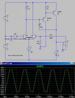
Attached below is a simplified simulation schematic (using an ideal unity gain output stage) of an amplifier front end typical of many designs and by no means a worst case example.
The amp is rated at 100W into 8 ohms, so its peak output voltage swing at rated power is 40V.
The LTP is provided with simple resistive loading instead of a current mirror. The load resistor is valued at 2700 ohms and passes approximately 0.5mA with the buffered VAS biasing voltage across it.
In order to ensure current balance in the LTP, the LTP is given a tail current source of 1mA.
Cdom is typical at 100pF.
Because of the low tail current of the LTP to drive Cdom, this design only slews about 5.5V/us. The triangular waveform in the picture attached below is the amplifiers 20kHz squarewave response.
This amplifier can only just pass a full power 20kHz sinewave with out slewrate-limiting induced distortion.
Because of this, the amp may even measure quite OK in terms of THD-20 at full power, but any sufficiently fast and large transient in an audio signal will instantly overdrive the LTP and cause hard TIM and massive temporary distortion of the entire audio signal.
Miller compensation is fine, so long as you have a high enough LTP tail current to drive Cdom for a given power output.
Attachments
Hi G,
your observations show that the technical performance is perfectly adequate when Miller comp cap is used correctly. I cannot disagree with that. Doug Self goes to great lengths to prove and measure exactly that.
I said, I believe the amp sounds better if the alternative feedback cap is fitted in lieu of the Miller comp cap.
G.Kleinschmidt said:[snip]
Miller compensation is fine, so long as you have a high enough LTP tail current to drive Cdom for a given power output.
Hi Glen,
True, but there is one more point: The input stage has to deliver all the current that goes through the Miller cap. In your example at full power and 20kHz, about 0.5mA. At this relative high current, the input stage will considerably contribute to distortion.
If the Miller cap is connected to the inverting input, this current will be much lower (10uA or so), resulting in far less distortion from the input stage.
Cheers,
Edmond.
AndrewT said:I said, I believe the amp sounds better if the alternative feedback cap is fitted in lieu of the Miller comp cap.
Yes, and in line with what you said, I gave an practical example typical of many marginal designs out there that CAN conceivably benefit sonically from having a lower value Miller compensation capacitor fitted.
To say as a general rule that any Miller compensated amp will magically sound better if the Miller cap is reduced in value with the addition of lead compensation is bunkum.
Edmond Stuart said:
Hi Glen,
True, but there is one more point: The input stage has to deliver all the current that goes through the Miller cap. In your example at full power and 20kHz, about 0.5mA. At this relative high current, the input stage will considerably contribute to distortion.
If the Miller cap is connected to the inverting input, this current will be much lower (10uA or so), resulting in far less distortion from the input stage.
Cheers,
Edmond.
Hi Edmond. I agree, but my example was a deliberately marginal design. In a proper Miller compensated amp in which the LTP has a high enough tail current to deliver a slew rate for a power bandwidth of, say, 200kHz or so, then the increase in HF input stage distortion caused by the miller cap loading will be generally next to negligible.
Slightly off topic: another bug of mine - declarations as to what is acceptable in terms of slewrate for power amplifiers without any mention of the relationship to power output and output voltage swing.
Cheers,
Glen
Glen,
As a rule of thumb I'm using the following formula to calculate the required minimum value of the tail current:
I=3×2×Pi×Cdom×f×Vp
Then at 40V output using 100pF Cdom at 20.000kHz signal we need at least 1.5mA. In practise I'm using somewhat more tail current for better transient-response and to increase slew-rate performance of the amplifier. In this case I'd operate the LTP even at 3mA.
Edmond,
Why?
Andrew,
You mean lead cap as "alternative feedback cap"?
OK guys, another lag comp. vs. lead comp. contention!")
As a rule of thumb I'm using the following formula to calculate the required minimum value of the tail current:
I=3×2×Pi×Cdom×f×Vp
Then at 40V output using 100pF Cdom at 20.000kHz signal we need at least 1.5mA. In practise I'm using somewhat more tail current for better transient-response and to increase slew-rate performance of the amplifier. In this case I'd operate the LTP even at 3mA.
Edmond,
At this relative high current, the input stage will considerably contribute to distortion.
Why?
Andrew,
I said, I believe the amp sounds better if the alternative feedback cap is fitted in lieu of the Miller comp cap.
You mean lead cap as "alternative feedback cap"?
OK guys, another lag comp. vs. lead comp. contention!
Andy L. Francis said:Glen,
As a rule of thumb I'm using the following formula to calculate the required minimum value of the tail current:
I=3×2×Pi×Cdom×f×Vp
Then at 40V output using 100pF Cdom at 20.000kHz signal we need at least 1.5mA. In practise I'm using somewhat more tail current for better transient-response and to increase slew-rate performance of the amplifier. In this case I'd operate the LTP even at 3mA.
Hi Andy.
I like 10:1 rules of thumb.
If we design an Miller compensated amplifier with enough LTP tail current for a power bandwidth of 200kHz instead of 20kHz, then we ensure that the slewrate is more than adequate for the given output voltage swing and that the increase in input stage distortion due to Cdom loading is also small.
In my circuit example above, this would require a LTP tail current of ~10mA, which may seem impractically large.
However, if we remove the simple load resistor and replace it with a current mirror, the full tail current is available for actively driving the Miller capacitance in both directions, so the slewrate doubles and the LTP tail current requirement drops down to 5mA.
Cheers,
Glen
- Home
- Amplifiers
- Solid State
- Bob Cordell Interview: BJT vs. MOSFET