Hi Nelson,
You aren't using it, therefore I doubt it has potential or you have progressed far beyond that.
-Chris
So, how does it sound?And here's a variation on the theme:
You aren't using it, therefore I doubt it has potential or you have progressed far beyond that.
-Chris
Re: Re: weak inversion
Hi Charles,
I don't consider myself much of a device guy, but I think there are actually three regions of operation to consider. The square law region is in the middle, at medium currents, The exponential sub-threshold region is at very low currents. Then, at higher currents there is a departure from the square law as a result of the effective channel resistance. So in other words, the square law gets violated on both sides. I do remember back in the 1970's hearing a couple of papers presented at ISSCC talking about how the MOSFETs (small-signal at the time) sort of began acting bipolar-like at very low currents.
Cheers,
Bob
Charles Hansen said:
Edmond, thank you for your patience. Please know that it has not been my intention to offend you.
Your attached graph from Philips for the IRF640 shows very clearly that the departure from square law occurs at relatively high current levels that will affect the crossover distortion in an audio amplifier. This device is a bit smaller than would normally be used for an audio output stage, so the effect would be even more pronounced in a typical device used for an audio amplifier.
I had always (and apparently mistakenly) thought that this effect only happened at much lower current levels. If I am understanding the attachment to Dimitri's post just below yours, it looks like the departure from square law is occurring at a level of around 5 uA, which was more in line with my understanding. But perhaps this graph is for a small signal device and therefore not applicable to the subject of the output stage. Thank you for clearing this up for me.
My thanks to both you and Andy for explaining this subject in detail and answering my questions. I have benefited from this and am sure that many others have as well.
Hi Charles,
I don't consider myself much of a device guy, but I think there are actually three regions of operation to consider. The square law region is in the middle, at medium currents, The exponential sub-threshold region is at very low currents. Then, at higher currents there is a departure from the square law as a result of the effective channel resistance. So in other words, the square law gets violated on both sides. I do remember back in the 1970's hearing a couple of papers presented at ISSCC talking about how the MOSFETs (small-signal at the time) sort of began acting bipolar-like at very low currents.
Cheers,
Bob
weak inversion
Hi Charles,
Thank you for your kind response, despite my comment that was perhaps a little bit too harsh. As for the the minority carriers issue, that is, MOSFETs vs. BJT's, I'm in dubio, in particular since the arrival of the TT-BJTs. Because I have sooo many hours invested in MOSFETs output stages, it is (emotionally) difficult to switch back again to BJTs, but you never know, maybe I switch my mind.
Regarding a bridge amp, although a good idea, that's not an option for me, as I spent already a ridiculous amount of trannies (60!) for a half bridge amp.
Cheers, Edmond.
janneman said:Interesting. I'm sure you are aware of the latest D Self contraption, I think he called it class X, his design for, was it Musical Fidelity. He basically loads the output stage with a current to one of the supplies to offset the zero current xover away from zero signal xover.
Maybe another variation would be to have multiple parallel output stages, each loaded with a different current to a different supply polarity so each will go through zero current differently. But then how to combine those outputs... Hmm, probably need some diodes somewhere in that circuit...
Probably you are aware that I yawn at Self's latest effort, mostly
because I began selling that idea in '91 with the Aleph 0. It
was a pure Class A design however. While the approach also
works well with an AB push-pull stage, it is not so pretty with a
Class B output stage.
Also, I find that the bias modulation scheme with a negative
resistance characteristic is not as desirable as a general negative
impedance - in other words the modulation is dependent on the
output voltage, not the output current. As a result it works
perfectly for a specific resistive loads, but does not respond to
other values or load reactance. This choice may have been
dictated by the possibility of a patent, since there is prior art.
Since you mention it, we employ a single-ended bias + PP scheme
on the Pass Labs X product. As you may know, this is a balanced
circuit with cross-coupled error correction so that the circuit
seeks to replicate errors in phase at the loudspeaker terminals,
cancelling them differentially. Since both halves have a single-
ended bias as well as a push-pull bias, such crossover as does
exist occurs at different points in the two outputs, and this makes
it easier to correct since one of the stages is in the more linear
region at that point.
Not that this is much of an issue, since all the X amps operate at
very high push-pull bias anyway - there's not all that much to
correct.

anatech said:Hi Nelson,
So, how does it sound?
You aren't using it, therefore I doubt it has potential or you have progressed far beyond that.
I recall that it sounded quite good at the time, but that was back
when a 709 front end was still respectable.
I have occasionally mused over the notion of giving it a try.....
Naaaaaaaaahhhhh.....

There was a link that I posted a while back to a PowerPoint presentation from a Georgia Tech course on analog integrated circuit design. There's also a bunch of other interesting online information associated with that course as well, relating to device physics. The main page for the course is here. There are videos of the lectures here. These lectures talk about diode, MOSFET and BJT device physics, and cover sub-threshold as well as above threshold behavior for MOSFETs. The lectures are in the "Real Player" format. I don't recommend installing Real Player because of adware and other garbage it's been known to install. Instead, I'd recommend using Real Alternative. I'm not a device physics guy to say the least, so I got somewhat lost in parts of the lectures, but they are illuminating anyway.
Regarding the equations that join together the sub-threshold and square law regions, the simplest form of these I've seen are part of the documentation for the EKV model. The EKV model manual for version 2.6 is here. This model is supported in LTSpice and Micro-Cap. However, this manual seems to cover everything except the actual interpolation formula that joins the regions. That information is provided in equation 30 of this paper on the EKV model.
The manual for the BSIM3 model can be found here. My original thought was to use this info to try to extract the model parameters myself. But I found the information in this manual overwhelming, so I gave up on trying to extract parameters for it. Instead, I'm working on trying parameter extraction with EKV. There's an interesting comparison of the BSIM3 and EKV models (and another model called SP2001) here.
Re: weak inversion
Only 60 Edmond?!
I'm at about 200 per channel with my current 1kW+1kW baby. Unfortunately, I won't be playing amplifiers for a while though, becase a part of my daily-driver car broke, and I have used this as an excuse to stroke my V8 block out to an environmentally friendly 6.3 litres and to fit a much hotter camshaft, which should easilly put my daily driver into the 11 second standing 400m bracket. I guess this is slightly off topic though
Bye bye.
Oh, did I mention that my 1kW+1kW is in your favorite class A flavour? LOL
estuart said:Regarding a bridge amp, although a good idea, that's not an option for me, as I spent already a ridiculous amount of trannies (60!) for a half bridge amp.
Only 60 Edmond?!
I'm at about 200 per channel with my current 1kW+1kW baby. Unfortunately, I won't be playing amplifiers for a while though, becase a part of my daily-driver car broke, and I have used this as an excuse to stroke my V8 block out to an environmentally friendly 6.3 litres and to fit a much hotter camshaft, which should easilly put my daily driver into the 11 second standing 400m bracket. I guess this is slightly off topic though
Bye bye.
Oh, did I mention that my 1kW+1kW is in your favorite class A flavour? LOL
An externally hosted image should be here but it was not working when we last tested it.
Hi Glen,
For a while I drove a 12.5 sec '67 Olds Cutlass. Not good for day to day driving.
It's also the only car that scared the heck out of me. Only 331 cu inches required for torque galore. It started life as a 327.
In the end, I'm sorry I did that to that car, it was too nice. I'm not sorry for the experience.
So, you're at 200 outputs per channel? It's all heat sink and transformers! How much will it weigh???
-Chris
anatech said:Hi Glen,
For a while I drove a 12.5 sec '67 Olds Cutlass. Not good for day to day driving.
It's also the only car that scared the heck out of me. Only 331 cu inches required for torque galore. It started life as a 327.
Mine started as a GM 308 (an Australian designed and built engine). I currently have a peak flywheel torque figure of about 600Nm. Car currently does low 13's. The stroker kit I'm using will take the capacity out to 383cu in. I'm aiming for about 350 flywheel kilowatts.
anatech said:So, you're at 200 outputs per channel?
Oh no, ~200 BJT's in total (not only output devices)
anatech said:How much will it weigh???
Lots.
Cheers,
Glen
Just out of interest, some Sansui service manuals here:
http://www.classicsansui.net/Schematics.htm
With a few pages of this one (AU-X1) giving a brief write up on LAPT’s and crossover distortion:
http://www.classicsansui.net/images/Schematics/sansui au-x1 service manual 03.jpg
http://www.classicsansui.net/images/Schematics/sansui au-x1 service manual 04.jpg
Cheers,
Glen
Re: Re: weak inversion
Hi Glen,
Yes, you did already.
BTW, I have nothing against class-A as long as it doesn't produce heat or turns my electricity meter into a gyroscope.
So, nothing wrong with your approach.
Cheers, Edmond.
G.Kleinschmidt said:[snip]
Oh, did I mention that my 1kW+1kW is in your favorite class A flavour? LOL
Hi Glen,
Yes, you did already.
BTW, I have nothing against class-A as long as it doesn't produce heat or turns my electricity meter into a gyroscope.
So, nothing wrong with your approach.
Cheers, Edmond.
Nelson Pass said:
Probably you are aware that I yawn at Self's latest effort, mostly
because I began selling that idea in '91 with the Aleph 0. It
was a pure Class A design however. While the approach also
works well with an AB push-pull stage, it is not so pretty with a
Class B output stage.
Also, I find that the bias modulation scheme with a negative
resistance characteristic is not as desirable as a general negative
impedance - in other words the modulation is dependent on the
output voltage, not the output current. As a result it works
perfectly for a specific resistive loads, but does not respond to
other values or load reactance. This choice may have been
dictated by the possibility of a patent, since there is prior art.
Since you mention it, we employ a single-ended bias + PP scheme
on the Pass Labs X product. As you may know, this is a balanced
circuit with cross-coupled error correction so that the circuit
seeks to replicate errors in phase at the loudspeaker terminals,
cancelling them differentially. Since both halves have a single-
ended bias as well as a push-pull bias, such crossover as does
exist occurs at different points in the two outputs, and this makes
it easier to correct since one of the stages is in the more linear
region at that point.
Not that this is much of an issue, since all the X amps operate at
very high push-pull bias anyway - there's not all that much to
correct.
Nelson,
Thank you for that insight!
Of course I know that ingenious x-scheme.
You any part of that movie: "The X-men, the last stand" ?
Jan Didden
andy_c said:.......
Regarding the equations that join together the sub-threshold and square law regions, the simplest form of these I've seen are part of the documentation for the EKV model. The EKV model manual for version 2.6 is here. This model is supported in LTSpice and Micro-Cap. However, this manual seems to cover everything except the actual interpolation formula that joins the regions. That information is provided in equation 30 of this paper on the EKV model.
The manual for the BSIM3 model can be found here. My original thought was to use this info to try to extract the model parameters myself. But I found the information in this manual overwhelming, so I gave up on trying to extract parameters for it. Instead, I'm working on trying parameter extraction with EKV. There's an interesting comparison of the BSIM3 and EKV models (and another model called SP2001) here.
Hi Andy,
Thank you very much for these links. Very informative and useful. Probably I'll also switch to EKV. Far less parameters that make you mad.
Are you extracting the parameters for the 2SJ201/2SK1530 pair as well?
Anyhow, keep us informed about your progress, please.
Cheers, Edmond.
weak inversion
Hi Andrew,
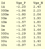
As I said already, I don't have the raw data of the Philips IRF640, but maybe you (and others) are interested in my measurement on the 2SJ201/2SK1530 (see below). Up to 30mA the figures are almost perfect exponential. From 100mA and higher they clearly deviate from the exponential relationship.
Cheers, Edmond.
PS: Maybe somebody else is willing to make a nice graph from these data (using splines) together with a true exponential curve and a quadratic one, as I'm not the mood to fiddle around with MatLab.
AndrewT said:Hi Estuart,
.............
Can you check the originals and confirm if or if not the plots are straight or slightly curved?
.............
Hi Andrew,
As I said already, I don't have the raw data of the Philips IRF640, but maybe you (and others) are interested in my measurement on the 2SJ201/2SK1530 (see below). Up to 30mA the figures are almost perfect exponential. From 100mA and higher they clearly deviate from the exponential relationship.
Cheers, Edmond.
PS: Maybe somebody else is willing to make a nice graph from these data (using splines) together with a true exponential curve and a quadratic one, as I'm not the mood to fiddle around with MatLab.
Attachments
Hi,
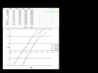
still not getting Irfanview to give the output I need, but hopefully this is legible.
Note the Pch drop away from exp @ 10uA. but just a hint for the Nch.
and that the Nchannel move away from exp much earlier @ >3mA.
Is there any significance in the difference in slope, 0.092 vs 0.077?
still not getting Irfanview to give the output I need, but hopefully this is legible.
Note the Pch drop away from exp @ 10uA. but just a hint for the Nch.
and that the Nchannel move away from exp much earlier @ >3mA.
Is there any significance in the difference in slope, 0.092 vs 0.077?
Attachments
Re: Re: weak inversion
Hi Glen,
I forgot to mention that we (Ovidiu and I, it's a joint project) are also using a common mode control loop in order to stabilize the standing current of the 'top' and 'bottom' VAS. It differs considerably from what I've dropped here a couple of month ago, a variation on your 12W amp:
http://www.diyaudio.com/forums/show...d=101745&perpage=10&highlight=&pagenumber=120 post#1194,
So, Glen and anyone else, ignore that thing. It is only thermally stable using well matched trannies. Although our new design is still based on the same principle, we had to redesign the amplifier completely. This is (partly) the reason why we need so many trannies.
Anyhow, preliminary test are very promising now.
Cheers, Edmond.
G.Kleinschmidt said:Only 60 Edmond?!
...........
Hi Glen,
I forgot to mention that we (Ovidiu and I, it's a joint project) are also using a common mode control loop in order to stabilize the standing current of the 'top' and 'bottom' VAS. It differs considerably from what I've dropped here a couple of month ago, a variation on your 12W amp:
http://www.diyaudio.com/forums/show...d=101745&perpage=10&highlight=&pagenumber=120 post#1194,
So, Glen and anyone else, ignore that thing. It is only thermally stable using well matched trannies. Although our new design is still based on the same principle, we had to redesign the amplifier completely. This is (partly) the reason why we need so many trannies.
Anyhow, preliminary test are very promising now.
Cheers, Edmond.
estuart said:Hi Andy,
Thank you very much for these links. Very informative and useful. Probably I'll also switch to EKV. Far less parameters that make you mad.
Are you extracting the parameters for the 2SJ201/2SK1530 pair as well?
Anyhow, keep us informed about your progress, please.
Cheers, Edmond.
Hi Edmond,
I've replied to your question in the SPICE thread, since it's a "SPICE only" kind of issue. The text before your question in that post just summarizes the relevant discussions in this thread to provide some context. So you may want to skip over that part, as it just repeats what's been said here.
Re: Re: Re: weak inversion
Ok Edmond, sounds good. Do you guys plan to show the finished circuit? I’d like to see it!
I’ll be stripping my engine down tomorrow morning, but it looks like I’m going to have a weekend without much to do (can’t really go anywhere until my motor is back together, and the machine shop isn't picking it up the block till Wednesday ).
I hope to get a major update on my web site for my 12W and 1kW amp projects done.
I’ve got a 48-transistor preamp and tone control circuit, along with a 8 transistor power supply to add to the 12W amp page for a start!
Cheers,
Glen
estuart said:
Hi Glen,
I forgot to mention that we (Ovidiu and I, it's a joint project) are also using a common mode control loop in order to stabilize the standing current of the 'top' and 'bottom' VAS. It differs considerably from what I've dropped here a couple of month ago, a variation on your 12W amp:
http://www.diyaudio.com/forums/show...d=101745&perpage=10&highlight=&pagenumber=120 post#1194,
So, Glen and anyone else, ignore that thing. It is only thermally stable using well matched trannies. Although our new design is still based on the same principle, we had to redesign the amplifier completely. This is (partly) the reason why we need so many trannies.
Anyhow, preliminary test are very promising now.
Cheers, Edmond.
Ok Edmond, sounds good. Do you guys plan to show the finished circuit? I’d like to see it!
I’ll be stripping my engine down tomorrow morning, but it looks like I’m going to have a weekend without much to do (can’t really go anywhere until my motor is back together, and the machine shop isn't picking it up the block till Wednesday
). I hope to get a major update on my web site for my 12W and 1kW amp projects done.
I’ve got a 48-transistor preamp and tone control circuit, along with a 8 transistor power supply to add to the 12W amp page for a start!
Cheers,
Glen
- Home
- Amplifiers
- Solid State
- Bob Cordell Interview: BJT vs. MOSFET