Putting in zero-ohm jumper resistors really would be bizarre if you already used a ton of wire links on the board as you see here. Unless you removed the resistors to check them as zero ohms, the marked value of 100k is more likely. I can't imagine it does much other than run a very low current device like a neon as Mooly suggests or perhaps an input for a mains monitor circuit, clock, timer display etc.
Usually, we now see tiny isolating transformers for maintaining standby circuits. Perhaps this is a cheap version for some related function.
Usually, we now see tiny isolating transformers for maintaining standby circuits. Perhaps this is a cheap version for some related function.

Resistors used as SPACERS
This thread deserves to be in construction tips and not lounge.
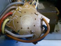
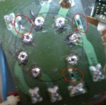
These are 100K and are used for raising the selector switch to increase the distance between the chasis and the wires, may be to accomodate the bends on the wire or to manage distance of the chasis from the mains wires.
You might have noticed there are some jumpers near the wire ends.
These are used for strengthening the copper pad. The solder on these jumpers give a thickness to the track and the jumpers hold it to the laminate. Notice that the jumper ends are bent on the solder side.
The lug(on the wire) also adds to the rigidity of the joint.
The ideas are for mechanical purpose but solved using pcb mfg technique.
Gajanan Phadte
This thread deserves to be in construction tips and not lounge.
These are 100K and are used for raising the selector switch to increase the distance between the chasis and the wires, may be to accomodate the bends on the wire or to manage distance of the chasis from the mains wires.
You might have noticed there are some jumpers near the wire ends.
These are used for strengthening the copper pad. The solder on these jumpers give a thickness to the track and the jumpers hold it to the laminate. Notice that the jumper ends are bent on the solder side.
The lug(on the wire) also adds to the rigidity of the joint.
The ideas are for mechanical purpose but solved using pcb mfg technique.
Gajanan Phadte
Attachments
Last edited:
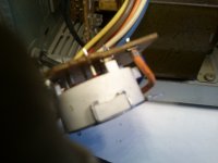
I was helping my friend to repair this, but then the primary itself is shorted/burnt. The selector switch was rotating freely. He has connected it to 230 and the switch must have repositioned itself to 100 or 117 volts due to the vibration from transporting it.
The jumpers near the wires...
I have seen this done in a different way in my TV. Earlier, I was thinking this is done to prevent cold solder but now I know it to be for the purpose in my above post.
They put a hollow brass rivet at the pad and solder the wire fitted with a lug. Prevents pad dislocation.
Gajanan Phadte
- Status
- This old topic is closed. If you want to reopen this topic, contact a moderator using the "Report Post" button.
- Home
- Member Areas
- The Lounge
- Bizarre use of resistors