The bilinear transform is often used to generate IIR digital filters in the "biquadratic" form. These can be used to implement the filter when the biquad coefficients can be directly entered into a DSP processor - for example the "advanced biquad" feature of the MiniDSP crossover lineup.
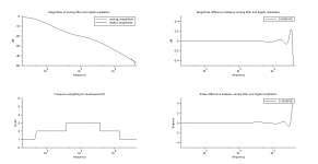
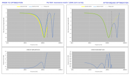
The response of the digital filter does not always match that of the analog filter prototype as the frequency approaches the Nyquist frequency. This is a side effect of the mapping of the frequency interval 0..Nyquist onto a circle as part of the bilinear transform. Below are two examples of the type of problem that can arise (sampling frequency = 48kHz):


It's clear from the above examples that there are significant differences within the audio band between the analog prototype and the IIR digital realization of the filter using the bilinear transform. One property of the bilinear transform is that the magnitude response must be symmetric about the sampling frequency. Additionally, the phase must be zero at the sampling frequency. This results from the mapping mentioned earlier, so that the function is continuous on the circle in the Z plane.
There is a way to improve the situation. You can not change the properties of the bilinear transform, however, you can try to minimize the differences between the analog prototype and the IIR digital filter below some frequency that is close to the Nyquist frequency. I have used this approach as part of a "biquad optimizer" that I have created, and that will be released with the next version of the Active Crossover Designer tools. For instance, the following filter responses are obtained (using the two examples shown above):


For these plots, the digital filter has been optimized so that the magnitude response matches the analog filter below 20kHz. There are still differences between the analog and digital magnitude responses, however, these have been held to 0.1dB or less. Deviations in the magnitude at higher frequencies are not important for a variety of reasons, such as lack of hearing sensitivity and the action of DSP anti-aliasing filters. The phase response has not been optimized and some differences remain. Since amplitude and phase are related, you cannot optimize both independently for an IIR filter.
I'm hoping that ACD users will find this a useful tool.
I welcome your comments and thoughts on this approach.
.
The response of the digital filter does not always match that of the analog filter prototype as the frequency approaches the Nyquist frequency. This is a side effect of the mapping of the frequency interval 0..Nyquist onto a circle as part of the bilinear transform. Below are two examples of the type of problem that can arise (sampling frequency = 48kHz):
It's clear from the above examples that there are significant differences within the audio band between the analog prototype and the IIR digital realization of the filter using the bilinear transform. One property of the bilinear transform is that the magnitude response must be symmetric about the sampling frequency. Additionally, the phase must be zero at the sampling frequency. This results from the mapping mentioned earlier, so that the function is continuous on the circle in the Z plane.
There is a way to improve the situation. You can not change the properties of the bilinear transform, however, you can try to minimize the differences between the analog prototype and the IIR digital filter below some frequency that is close to the Nyquist frequency. I have used this approach as part of a "biquad optimizer" that I have created, and that will be released with the next version of the Active Crossover Designer tools. For instance, the following filter responses are obtained (using the two examples shown above):
For these plots, the digital filter has been optimized so that the magnitude response matches the analog filter below 20kHz. There are still differences between the analog and digital magnitude responses, however, these have been held to 0.1dB or less. Deviations in the magnitude at higher frequencies are not important for a variety of reasons, such as lack of hearing sensitivity and the action of DSP anti-aliasing filters. The phase response has not been optimized and some differences remain. Since amplitude and phase are related, you cannot optimize both independently for an IIR filter.
I'm hoping that ACD users will find this a useful tool.
I welcome your comments and thoughts on this approach.
.
Last edited:
Hi Charly,
nice work!
There have been some discussions here in the forum regarding RIAA EQ design with IIR filters, dealing with the same problem (deviations from analog filter response when using bilinear transform). Robert Owen has achieved quite impressive results (and so did Scott Wurcer), also focusing on optimizing the magnitude response. His algorithm is not published but he explained in principle how he did it.
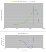
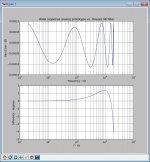
I also did some work in this area and used the FDLS Algorithm (Frequency Domain Least Squares) from Greg Berchin. This method achieves very good results for magnitude and phase however often needs some more Biquads. Attached you'll find some results for a RIAA EQ (FS 96kHz) using four Biquads. In my ADC I can use up to 8 Biquads so the higher number is no problem...
WOuld be nice to have a look at the latest version of your ACD tools")
nice work!
There have been some discussions here in the forum regarding RIAA EQ design with IIR filters, dealing with the same problem (deviations from analog filter response when using bilinear transform). Robert Owen has achieved quite impressive results (and so did Scott Wurcer), also focusing on optimizing the magnitude response. His algorithm is not published but he explained in principle how he did it.
I also did some work in this area and used the FDLS Algorithm (Frequency Domain Least Squares) from Greg Berchin. This method achieves very good results for magnitude and phase however often needs some more Biquads. Attached you'll find some results for a RIAA EQ (FS 96kHz) using four Biquads. In my ADC I can use up to 8 Biquads so the higher number is no problem...
WOuld be nice to have a look at the latest version of your ACD tools
Attachments
Hi Charly,
nice work!
There have been some discussions here in the forum regarding RIAA EQ design with IIR filters, dealing with the same problem (deviations from analog filter response when using bilinear transform). Robert Owen has achieved quite impressive results (and so did Scott Wurcer), also focusing on optimizing the magnitude response. His algorithm is not published but he explained in principle how he did it.
I also did some work in this area and used the FDLS Algorithm (Frequency Domain Least Squares) from Greg Berchin. This method achieves very good results for magnitude and phase however often needs some more Biquads. Attached you'll find some results for a RIAA EQ (FS 96kHz) using four Biquads. In my ADC I can use up to 8 Biquads so the higher number is no problem...
WOuld be nice to have a look at the latest version of your ACD tools
Hmmm, I never thought about using additional biquads - how many more are typically needed?
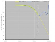
What I have observed is that the response deviations become significant around 0.1*Fs, which is about 5kHz for 48kHz sampling rate. Below this frequency the phase and amplitude are close to the analog response. Since this is above where you would typically cross over to a tweeter (at least I would not cross over so high) the phase deviation is no big deal. As a result I only concentrated on the amplitude response. I can set the maximum allowed deviation to be below a very small value (e.g. 0.05dB or less, see attached image, below) up to around 18-19kHz and this gives very satisfactory results using only one biquad. This also helps to improve the phase match between optimized IIR and analog responses at lower frequencies. I could probably include the phase response error below 0.1*Fs in my objective function to try and force that to be as close as possible as well. It would be easy to try...
Attachments
Last edited:
I'm posting an update on this with a few more plots. I'm hoping to release this tool in the near future.
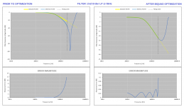
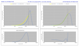
I'm not sure that people are aware that a standard DSP IIR filter biquad can stray away from its intended response characteristic at higher frequencies. Where (in frequency) this happens depends on the sampling rate - higher sampling rates (e.g. 96kHz and above) help to move the response deviations above the audio passband for the most part. Currently, since DSP audio engines running at 48kHz are becoming widespread, this problem is still prevalent and native/unoptimized DSP filters can have broadband deviations that would be audible. Using my approach, the difference between the intended (analog) filter prototype and the DSP realization can be reduced to very low levels (e.g. 0.1 dB) below a user-defined threshold frequency that is chosen to be high in the audio band (e.g. 18k Hz). Some examples are provided in the attached images.
The attached plots were generated using a standalone Excel spreadsheet with an optimization engine that I programmed in worksheet cells only - no VBA (works in Excel only - sorry Open/Libre Office users!).
Attachments
A link to the fully functional beta version:
CHARLIELAUB'S IIR BIQUAD OPTIMIZER TOOL
ABOUT THE OPTIMIZER / USAGE:
This was originally intended to accompany my ACD crossover designer tools. As a result, the inputs are meant to be taken from ACD, however, this is a stand-alone tool and does not need ACD to function. Anyone can play with the test function that appears when you open the spreadsheet. The file is in Excel 2003 xls format. The spreadsheet was developed on a machine running Office 2013, and should run on Excel Office 2007 version and later. If not please let me know. It may not work in Excel 2003 - if it does please let me know. I haven't yet done extensive testing, but it works well on everything that I have thrown at it so far.
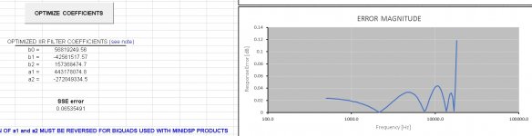
When you open the file you will see the input and control page. The inputs include the analog filter biquad coefficients that describe the response that is to be matched, as well as a guess for the digital filter coefficients that are to be optimized so that the digital and analog filter responses are as close to identical as possible. Initially the "optimized filter coefficients" output area will be blank and the analog and digital filter magnitude responses are plotted. For the built-in example I used an analog peaking (EQ) filter, +6dB, Q=1, centered at 15kHz.
Below the area where you enter the initial guess for the digital IIR biquad coefficients are input fields for the sampling frequency and the frequency range over which the filter will be optimized. The filters are evaluated on about 100 points that are spread out over this range. It's important to not set the high frequency too close to the Nyquist frequency (half the sampling frequency) as this area is very difficult to make exactly like the analog function. Since every DSP will use a steep anti-aliasing filter at the Nyquist frequency, deviations around and above this frequency are not important. I might use a value like 18kHz in this case but you can experiment with the end frequency to see how that influences the result. Do not set the start frequency too low either. In short, you want to concentrate on the frequency region where the analog and digital filter responses are differing to begin with, and then optimize that. In this case, and in general for a 48kHz sampling rate, I would choose 1kHz for the start frequency.
The button that runs to optimization code is next down the page. When you click this the code copies the initial digital IIR biquad guess to the cells that will eventually hold the "optimized" coefficients and then runs the SOLVER engine on these.
When the SOLVER is finished, the "optimized" coefficients are presented in the cells below the button. The analog and digital filters should be almost exactly the same below the end frequency of the optimization. You can consult the lower plot that shows the absolute values of the residuals to see the goodness of the fit. If the match is not good, check your values for the start and end of the optimization range, make sure the sampling rate is accurate, etc.
You can re-run the example problem over and over. Just delete the values in the cells for the "optimzed' coefficients. This resets the plots and everything is ready to run again. Tweak some parameters and see what happens.
You can always use b0=1, and the other initial guesses for the digital biquad coefficients set to zero. It's simply 0dB (unity gain) for all frequencies. This can result in faster optimization by SOLVER for some problems. In that sense it is also a biquad coefficients GENERATOR, meaning that you could enter any analog filter (its coefficients) and the SOLVER optimizer will generate the IIR biquad coefficients to match it. This may lead to some new IIR filter design methodologies...
I will post how to get the analog and digital input values for the biquad optimizer out of the ACD spreadsheets in a follow up post. For now, have fun with the test problem or any other that you are able to provide.
CHARLIELAUB'S IIR BIQUAD OPTIMIZER TOOL
ABOUT THE OPTIMIZER / USAGE:
This was originally intended to accompany my ACD crossover designer tools. As a result, the inputs are meant to be taken from ACD, however, this is a stand-alone tool and does not need ACD to function. Anyone can play with the test function that appears when you open the spreadsheet. The file is in Excel 2003 xls format. The spreadsheet was developed on a machine running Office 2013, and should run on Excel Office 2007 version and later. If not please let me know. It may not work in Excel 2003 - if it does please let me know. I haven't yet done extensive testing, but it works well on everything that I have thrown at it so far.
When you open the file you will see the input and control page. The inputs include the analog filter biquad coefficients that describe the response that is to be matched, as well as a guess for the digital filter coefficients that are to be optimized so that the digital and analog filter responses are as close to identical as possible. Initially the "optimized filter coefficients" output area will be blank and the analog and digital filter magnitude responses are plotted. For the built-in example I used an analog peaking (EQ) filter, +6dB, Q=1, centered at 15kHz.
Below the area where you enter the initial guess for the digital IIR biquad coefficients are input fields for the sampling frequency and the frequency range over which the filter will be optimized. The filters are evaluated on about 100 points that are spread out over this range. It's important to not set the high frequency too close to the Nyquist frequency (half the sampling frequency) as this area is very difficult to make exactly like the analog function. Since every DSP will use a steep anti-aliasing filter at the Nyquist frequency, deviations around and above this frequency are not important. I might use a value like 18kHz in this case but you can experiment with the end frequency to see how that influences the result. Do not set the start frequency too low either. In short, you want to concentrate on the frequency region where the analog and digital filter responses are differing to begin with, and then optimize that. In this case, and in general for a 48kHz sampling rate, I would choose 1kHz for the start frequency.
The button that runs to optimization code is next down the page. When you click this the code copies the initial digital IIR biquad guess to the cells that will eventually hold the "optimized" coefficients and then runs the SOLVER engine on these.
When the SOLVER is finished, the "optimized" coefficients are presented in the cells below the button. The analog and digital filters should be almost exactly the same below the end frequency of the optimization. You can consult the lower plot that shows the absolute values of the residuals to see the goodness of the fit. If the match is not good, check your values for the start and end of the optimization range, make sure the sampling rate is accurate, etc.
You can re-run the example problem over and over. Just delete the values in the cells for the "optimzed' coefficients. This resets the plots and everything is ready to run again. Tweak some parameters and see what happens.
You can always use b0=1, and the other initial guesses for the digital biquad coefficients set to zero. It's simply 0dB (unity gain) for all frequencies. This can result in faster optimization by SOLVER for some problems. In that sense it is also a biquad coefficients GENERATOR, meaning that you could enter any analog filter (its coefficients) and the SOLVER optimizer will generate the IIR biquad coefficients to match it. This may lead to some new IIR filter design methodologies...
I will post how to get the analog and digital input values for the biquad optimizer out of the ACD spreadsheets in a follow up post. For now, have fun with the test problem or any other that you are able to provide.

I just happened upon a related topic. There is a paper here by Orfandis called "Digital Parametric Equalizer Design With Prescribed Nyquist-Frequency Gain". Orfandis describes the same problem that I do above, and provides some closed form solutions for EQ.
My approach can be used for any deviation near the Nyquist frequency of an IIR DSP filter from the analogous analog filter, so it solves the same problem but has more general applicability.
My approach can be used for any deviation near the Nyquist frequency of an IIR DSP filter from the analogous analog filter, so it solves the same problem but has more general applicability.
Doesn't run for me. "SolverReset" macro issue. I have macro's enabled but apparently need to add another one?
Dave.
Is the SOLVER add-in enabled in your Excel?
What version of Excel are you using? Supposedly the code will work in Excel 2007 and 2013... I have only 2003 and 2013 here.
I should probably re-save the file with the xlsm extension to make this more clear. Then repost.
Last edited:
Doesn't run for me. "SolverReset" macro issue. I have macro's enabled but apparently need to add another one?
Dave.
Same here
EDIT - fixed, browsing for the solver found nothing but checking the box worked, double thumbs up to you!
FILE - OPTIONS - ADD-INS - Manage ad-ins - (check) Solver
Last edited:
The other odd thing that I have seen mentioned about calling solver from VBA when solver has never been used before (e.g. was not installed before) is that until it is used once manually some initialization/registration process is not executed. Using (opening? running?) solver once time from the menu supposedly does the trick. It's some kind of quirk of Excel add-ins I guess. This is another thing to try if you cannot get it to run from the button.
Also, to clarify the error message you (Dave) received, the "SolverReset" macro is part of the SOLVER add-in. Even if you allow macros to run in general, but don't have the SOLVER add-in installed/enabled, Excel has no idea what the SolverReset macro is, and therefore throws the error.
Also, to clarify the error message you (Dave) received, the "SolverReset" macro is part of the SOLVER add-in. Even if you allow macros to run in general, but don't have the SOLVER add-in installed/enabled, Excel has no idea what the SolverReset macro is, and therefore throws the error.
Last edited:
@charlie
Having problems with simple low pass/high pass where a0 or a2 are 1 and the others 0, results look very wrong. BTW I think the Q in the given example is 1.414.
H(s) = 1 / (s^2 + s/Q + 1) or H(s) = s^2 / (s^2 + s/Q + 1)
I could be doing something stupid, what a's and b's are in your 2nd order 5k example.
Last edited:
Just FYI two biquads can do 48K RIAA here are the poles and zeros in the z domain. I have no idea if the order makes any difference so you can make up different pairs and try. To get the a's and b's you need to make a polynomial out of a pair of poles or zeros (s+p1)*(s+p2) for each. You will need to fiddle with the gain too.
Poles = [-0.5753629759584974, -0.18809022271649045, 0.757443070241577, 0.9934698371024246]
Zeros = [-0.6147170033776734, -0.2762505206840416, -0.04727542059033789, 0.9365830834522171]
Result below.
Poles = [-0.5753629759584974, -0.18809022271649045, 0.757443070241577, 0.9934698371024246]
Zeros = [-0.6147170033776734, -0.2762505206840416, -0.04727542059033789, 0.9365830834522171]
Result below.
Attachments
Last edited:
Your equation for the transfer function
If you look at this pdf file about transfer functions:
http://opencourseware.kfupm.edu.sa/colleges/ces/ee/ee303/files\3-Lesson_Notes_Lecture_18.pdf
section 1 gives the form of a lowpass filter that you want to use in the analog section. The highpass form is a few pages later.
I find the filters obtained through this web page to be useful. Each will compute the TF coefficients for you if you supply Fc and Q. Check out:
Filter Design and Analysis
Note that, for first order filters, the coefficients for s^2 and/or z^-2 terms will just be zero.
I should have shown the form of the transfer function that I am using to define the a's and b's as there is no standard convention. Sorry about that. I have shown the transfer functions below.
IIR digital biquadratic transfer function:
analog biquadratic transfer function:
For the analog transfer function of lowpass and highpass filters, a1=Wo/Q and a2=(Wo)^2 where Wo is the corner frequency in radians, or Wo = 2*pi*Fc where Fc is the corner frequency in Hertz. Returning to what you posted, it should look like this:
H(s) = (Wo)^2 / (s^2 + s*Wo/Q + (Wo)^2) or H(s) = s^2 / (s^2 + s*Wo/Q + (Wo)^2)
is something like a prototype filter.H(s) = 1 / (s^2 + s/Q + 1) or H(s) = s^2 / (s^2 + s/Q + 1)
If you look at this pdf file about transfer functions:
http://opencourseware.kfupm.edu.sa/colleges/ces/ee/ee303/files\3-Lesson_Notes_Lecture_18.pdf
section 1 gives the form of a lowpass filter that you want to use in the analog section. The highpass form is a few pages later.
I find the filters obtained through this web page to be useful. Each will compute the TF coefficients for you if you supply Fc and Q. Check out:
Filter Design and Analysis
Note that, for first order filters, the coefficients for s^2 and/or z^-2 terms will just be zero.
I should have shown the form of the transfer function that I am using to define the a's and b's as there is no standard convention. Sorry about that. I have shown the transfer functions below.
IIR digital biquadratic transfer function:
Code:
               b0 + b1*z^-1 + b2*z^-2
    H(z) =  --------------------------
               a0 + a1*z^-1 + a2*z^-2
analog biquadratic transfer function:
Code:
               b0 + b1*s + b2*s^2
    H(s) =  ---------------------
               a0 + a1*s + a2*s^2
For the analog transfer function of lowpass and highpass filters, a1=Wo/Q and a2=(Wo)^2 where Wo is the corner frequency in radians, or Wo = 2*pi*Fc where Fc is the corner frequency in Hertz. Returning to what you posted, it should look like this:
H(s) = (Wo)^2 / (s^2 + s*Wo/Q + (Wo)^2) or H(s) = s^2 / (s^2 + s*Wo/Q + (Wo)^2)
Last edited:
Your equation for the transfer function
is something like a prototype filter.
Yes, your order is the reverse of the Python poly() function output my bad for not noticing. As Bob Orban pointed out this is an ill conditioned problem I can confirm there are lots of local minima. I am interested in how the Excel solver does and I wonder how the Python Scipy optimizers do.
Last edited:
Sorry to bug you again but I got the correct response just two pole low pass at 10K, 96K sampling Q = .5 but the coefficients make no sense.
Not bugging at all. Here are my thoughts:
You are correct that this is an ill-conditioned problem. Can't guarantee that there is a solution. Even if there is a solution, like in the case you demonstrated, there is no guarantee that it is a STABLE realization. Keep in mind that the poles must be inside the unit circle or... BOOM! There is a way to check that this condition but I can't recall it off the top of my head. I could add this into the code once I figure out how to do it. But for filters with no peaking or gain, the following should hold for the IIR biquad coefficients:
-1.0 < a0, a2 and b2 < 1.0
-2.0 < a1, b1 < 2.0
If you start with b0=1 and b1=b2=a1=a2=0 the SOLVER can wander off and find some very sub-optimal minimum. For this reason I enter the IIR biquads that are generated using the bilinear transform, for instance this well-known web page has formulas by Robert Bristow-Johnson for many filter types for IIR biquads:
http://www.musicdsp.org/files/Audio-EQ-Cookbook.txt
The way I get the input data is to generate the coefficients for both the analog TF and IIR digital TF from my Active Crossover Designer tools. You can down load them here (includes documentation):
http://audio.claub.net/software/ACD/ACD_RELEASE_2.0.zip
Open a blank System Response Template, enter the filter of interest on the System Info sheet, enter the sample rate on the BiquadCalcs sheet cell B22. In the Filter_TF_Calcs sheet columns B thru G contain the analog transfer function coefficients for Filter 1..6 in rows 11 thru 16. Likewise, columns T thru AE contain the IIR digital transfer function coefficients in rows 12 thru 16, from top to bottom: b0, b1, b2, a1, a2. These are ready to copy and then paste into the optimization worksheet.
This is all in a beta form now, so it's not very user friendly. But hopefully this gives you at least some hints on where to get the input data.
Keep in mind that the deviation between the analog frequency response and the frequency response for the analogous bilinear-transform-generated IIR digital filter will be very low as you get below 0.1*Fs for any filter. It's only in the case the the filter gain is different than 1.0 (0dB) above 0.1*Fs that you can start to see some differences. I have tried to highlight some of the more extreme examples of this. Not every filter has to be optimized, however, and you could just design your crossover with the IIR filter responses in the first place. As long as you will only implement the crossover using IIR digital means, you are all good.
- Status
- This old topic is closed. If you want to reopen this topic, contact a moderator using the "Report Post" button.
- Home
- Source & Line
- Digital Line Level
- Biquad Optimizer for IIR digital filters