The sensitivity of your loudspeakers and your system's total voltage gain and listening distance plus background quietness will play a major role in that test. Noise in applications is always relative. Best engineering goal should be 'adequate' noise level in any specific application than absolute minimum IMHO.
Good point, I will reference against a real music input played at a suitable level and possibly played very loud. I should be then able to refer this back to an S/N figure, and as you suggest I may very well find that using a single input device is adequate and paralleling trannies and opamps in the quest for a lower noise MC input is a quest too far and that energy might be better expended else where. Which would be a good result
i believe I have have 3 or 4 each of the 2SD786 and 2SB737 Rohm around that I bought from Erno Borbely in the 1980s for his phono stage that I never finished. some were soldered in with trimmed leggs but never powered and some are spares - i'd sell them for $30 plus shippping. i'll count what I have if anyone's interested.
Lashed up a breadboard test on 2SA2547 MC preamp the other day and cct all working OK, but a lot of electrical pickup from lighting etc and limitations of test set meant that I need a special additional gain stage and some proper shielding to make a realistic noise measure.
Today built an input stage noise XL sheet and poking the 0.5nV /rtHz of 2SA1085 into it at the stated parameters back calculates to something of the order of rbb' 15R
Today built an input stage noise XL sheet and poking the 0.5nV /rtHz of 2SA1085 into it at the stated parameters back calculates to something of the order of rbb' 15R
Not surprisingly, 0.5 nv/rt-Hz is approximatly the Johnson (thermal) noise of a 15 Ohm resistor.
Well spotted, the test conditions on the data sheet specify an Rs of zero which nails current noise. Ic is specified at 10mA which reduces the shot noise component of en to an insignificant level which leaves the Johnson noise of rbb'. QED
Interestingly, I checked my Linn Troika at 2R ( 150, 200 uA? )and my Goldring ? at 9R (approx 500uA.)
Using required gain and real amplifiers, common emitter, common base ( cascode) and parallel op amps in spreadsheet noise calcs, what will work for one will not work for the other. I treated parallel transistors as a single device with rbb' simply divided by the number of parallel devices.
I have always thought that transistor matching is unimportant, and now looking analytically I believe that is correct ( tell me if I am wrong). and that attempts by Naim et al to balance collector currents was always misguided. Shot noise is not dependent on any individual device and so it does not matter whether all the current flows through one device or is shared. So long as each parallel transistor carries some current, even a tiny bit, then the rbb's are in parallel and so the Johnson noise calc stands.
In a cascode preamp with an Rs of 9R any collector current above say 2mA and the noise current component is dominating the figures.
Ideally the Rfb ( feedback resistor ) needs to be kept no larger than Rs and DC blocking capacitor is becoming HOOOOGE, or must be a avoided.
In this situation the best circuit I have is Nat Semi AN222, but once the currents and O/P gain are increased for a low O/P cartridge then distortion begins to suffer ( according to a SPICE simulation)
Against an Rs of 2R then the NF is going to be bad, ie. 9dB but that is still around the 0.5nV/rtHz.
So I come back to opamps. AD797's ( in the plural) 3 or 4 used in parallel even with Rfb of 4.7R or 10R will come out at a composite equivalent en of 0.5nV/rt Hz and so long as supply decoupling is correctly dealt with, no tantrums and vanishingly low distortion and no seriously bulky C's.
I have tried THAT 300 array of four NPN transistors as well as MAT02FH in this circuit.
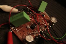
With the THAT 300 I experienced a high sensitivity against high frequency breakup and hum. It picked up a lot of noise. It took some half hour to cure this. In the end I installed a parallel combination of 330 Ohms with 15nF from each plus or minus input (remember both are floating) to ground. I also put the substrate of the THAT module to ground. As this device was unused, I gave it some hours before I was sure that the sound was not related to missing burn-in. The 2SC2546 I used before had been used years ago as well as the MAT02FH, but I will come to the MAT later.
The sound of the THAT was unpleasant, downward nasty. Lean, shallow bass, shallow soundstage, wirey treble, edgy midrange. Maybe there was still some HF leftover ... no wonder if one reads the datasheet. 350Mhz at 1mA is fast like hell.
Enter the MAT02FH. Immediately there was some relief. It sounds right OK from the start. It sounds more correct than the 2SC2546, one can notice that bass is tighter, but there was some idleness in the musical presentation, bordering the impression of boringness. Treble was less fine as with 2SC2546, and midrange less transparent. BTW, I had nearly the same impressions when I used them in discrete op amp style preamp modules a decade or one and a half ago.
Next to try: LM394, 2SD786, 2SC2240. Maybe I reverse the polarity for 2SB737.
Hartmut
Attachments
Hi Hartmut,
good thread, and I will follow it with interest.
But, at least for me, there is no way around jfets for MC-input. It is the only choice for a virtually DC-less input stage without compromises.
One might consider input transformers, but ... well ... show me a acoustically transparent one...
I did experiments with common base input stages myself, and could never guarantee not getting some DC offset at the input sooner or later. Plus, I found the sound of a complementary jfet input stage, both with a folded cascode or normal cascode topped with a current mirror (pass style) better in terms of bass firmness, resolution and magic (c) when used open loop. Even with feedback (syn08's HPS) could be made sounding quite good.
I support your findings vs. stiffness of working points, but not vs. mirroring.
However, I know you have a sharp ear, so your findings will be of interest for me!
Rüdiger
Hello Ruediger,
I have many years ago tried SK170/240/146 and the like in common source configuration, with a resistor as load, no cascode at all ... among these usual suspects, I liked the 2SK97 best (see the 1995 Kaneda preamp), but what I missed with all these JFETs was naim style tightness, grip and PRAT. Since I had some lucky years with naim and naim copies in 80ies, I got used to what naim does right, and I am reluctant to pass on this (no pun intended!).
Though, as you mention bass tightness with your proposed configuration, I think I will give it a try this week. I still have a JFET moving coil stage here, have to add a cascode only.
Thanks a lot.
Hartmut
Hallo Hartmut,
If you need 2SA1316 and 2SC3329 for testing, please send me a PM.
With kind regards.
Sam
Hi Sam,
Thanks, email sent.
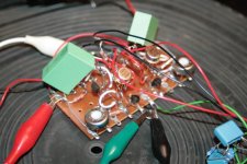
This is the current list of bipolars tried these days in above configuration, in order of personal preference, best liked on top:
2SC2546E
2SD786R (cpl. to 2SB737R)
LM394CH
MAT02FH
2SC3381
I just changed back from 2SD786R to 2SC2546E, to experience the difference, they are quite close. The 2SC2546E is a touch more transparent, while the 2SD786 has a bit more bass grip, but sounds a bit grey in midrange compared to the other.
After trying some two other transistors, I will start to develop the circuit:
- symmetrical loading of input transistors for lower offset (Early voltage!), there is 0.6V difference in Vce between the input transistors currently
- either folded cascode for simple moving coil stage
- or differential with some gain, also some degeneration, for first stage of a complete phono stage
- second stage (be it cascoded or differential) loaded by current mirror, with output load resistor, eliminating the output cap, with DC servo.
BTW, EMT uses the LM394CH in symmetrical common base configuration in the moving coil stage for their EMT 938 turntable. EMT fans prefer step-up transformers in this place, though.
best regards,
Hartmut
Last edited:
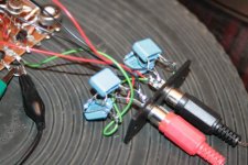
.............I started with 4 Volt rails, instead 12V, and gradully increased the voltage. At all voltages, I measured the voltage offset at the emitters of the two input trannies. Unfortunately, at rails > 8V, there was an increasing offset > 50mV, so did not dare to use this with my delicate Ortofon MC7500 cartridge.
.....
This is a shocking high value. Even 5mV would be extremely high. Given the circuit, it seems strange that such a high voltage can develop between the two emitters.
Looking at the picture, i can see that you did not thermally couple the input transistors. Also, you should match them for beta and Vbe at the current you are using them in the circuit. Use low tempco emitter resistors.
Check this thread, what John Curl and others are saying about a similar approach: MC pickup under current...how much is OK?
yeah, the offset voltage is something to consider. At 6V rails, and with 0.6Volts offset at the collectors, there is about 5mV Vee at open inputs. When a cartridge has been connected, this voltage divides between 2 times Re and Rcart. In my example 2*13 Ohms (at 3mA Ie) and 6 Ohms of the Ortofon MC7500 catridges. So only 1 mV of the initial offset is present at the cartridge leads, leading to 0.16mA bias current through a 5000 DEM (3000 USD) top of the line MC cartridge. This should not fry the coils. So far the results are very good, subjectively. If the subjective sonic results will improve, once this offset voltage and current have dissappeared, will be be interesting aspect of further experiments.
Hartmut
Hartmut
Hello Ruediger,
I have many years ago tried SK170/240/146 and the like in common source configuration, with a resistor as load, no cascode at all ... among these usual suspects, I liked the 2SK97 best (see the 1995 Kaneda preamp), but what I missed with all these JFETs was naim style tightness, grip and PRAT. Since I had some lucky years with naim and naim copies in 80ies, I got used to what naim does right, and I am reluctant to pass on this (no pun intended!).
Though, as you mention bass tightness with your proposed configuration, I think I will give it a try this week. I still have a JFET moving coil stage here, have to add a cascode only.
Thanks a lot.
Hartmut
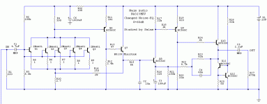
Since you liked Naim, I have done an overhaul of NA323 on simulation only, with easy to get, cheap transistors, but the parallel quintet input stage (biased at 1mA each in this version) can host Hitachi, Toshiba, and ROHM also. R1 is the cart's load, can change value of course. With this is I wanted to modernize the classic towards a much smoother HF response, more bass extension, more bandwidth, more gain, and far less input noise. Also I realigned it so it can use practically small coupling values and be able to work with film capacitors and not those trademark bottleneck tantalums. Maybe its interesting to you, I don't know. I have in mind to try it at a point too. It looks solid on the simulator but nobody knows if it will need some debugging in practice. Best of luck with all your experiments in any case!
Attachments
Salas,
this was exactly, how I started DIY in mid 80ies. My first "project" was a DIY variant of LM317 equipped Naim power supply (Snaps, Hicap), with two regulators in series, like Naim realized many years later in the Supercap. My changes to the naim circuits itself have been less successful, maybe naim had found the single sweet spot for this vintage circuit.
I focussed on differential inputs in preamps later, and my power amps are not that far away from the AKSA or destroyer circuits known in this forum.
Well I want it all, naim grip, but also low distortion, max transparency, fine detail at the same time.
There are some DIYer who make alternate boards for Naim, either commercial or group-buy folks, you can meet them on the pinkfishmedia forum. IIRC, the "Starfish" is a state-of-the-art version of the naim line stage. Today I don't care about bodging with naim any more, just have some of the cute half width vintage naim components in the living room for family.
Hartmut
Finally, I had to install my long-time favourite 2SC2240, and also the 2SC3329 that Sam had sent to me (thanks a lot!).
So in the end, I found an alternative to the 2SC2240. Ironically, this is not a special low-noise (low en) transistor.
Upated current top list, best liked on top
2SC3329
2SC2240
2SC2546E
2SD786R (cpl. to 2SB737R)
LM394CH
MAT02FH
THAT300
2SC3381
Hartmut
So in the end, I found an alternative to the 2SC2240. Ironically, this is not a special low-noise (low en) transistor.
Upated current top list, best liked on top
2SC3329
2SC2240
2SC2546E
2SD786R (cpl. to 2SB737R)
LM394CH
MAT02FH
THAT300
2SC3381
Hartmut
2SC3329 is very low noise. 0.6nVrtHz 2 Ohm rbb'.
oops, you are right, I have mixed up some datasheets.
I got too many things to try in my setup (different horns, woofers, tonearms), so I kept this moving coil stage constant for several weeks.
Though when I got a currently hyped moving coil cartridge for a week of home testing, and suspected a frequency anomaly, I took measurements of this moving coil stage with cartridge, using the Hifi News + Records test LP pink noise track, and had a look at the ARTA spectrum analyzer at line level. For the pink noise slope I made a compensation file.
I found an enormous deviation in the FR compared to high-Z loading, transformer loading, or 47k loading (Moving Magnet input).
With an operating point of 3.5mAmps each transistor there was a recessed midrange of about several dB compared to bass, and then a rising output above. The total deviation was 40dB. At 1mAmps each transistor the deviation went down to 30dB.
I also checked another cartridge, and coincidently, it showed exactly the same characteristic.
So I have to conclude, that zero-impedance or even low-impedance loading is not applicable to most MC cartridges.
While the sonic results are very attractive, and even visitors had positive reactions during the time I had this MC stage running - the deviation came not as extra nasty treble, but as extra detail and transparency - I make a stop here, and I have to change my moving coil stage in order to make it measure with MC catridges and sound good at the same time.
I will add some FR graphs later.
Hartmut

- Status
- This old topic is closed. If you want to reopen this topic, contact a moderator using the "Report Post" button.
- Home
- Source & Line
- Analogue Source
- Bipolars for low noise input - Alternatives to 2SC2240