AndrewT said:This is a put down that is disrespectful and unwarranted.
Keep personalities out of a technical discussion. There are far too many others that drop to this level in their discussion. I don't think we need to take this thread in that direction.
Andrew,
I have no idea why this would be personal or unrespectfull or unwarranted? Kirchoff's law is what applies here, and the last part is a famous quote from Ludwig von Bolzmann which I like.
Certainly nothing personal or disrespectfull intended.
Jan Didden
Yes, I disagree with that.
I wonder what value of R5 is fitted?
1k0 or 10k or something else?
The CCS + Ir5 = lab supply current.
the CCScurrent is dependanrt on Vbe of Q5 at the CCS current, on the Vf of LED @ it's current (determined by Vsupply and R3 + R5) and on R6.
if red LED Vf=1.55V and R6=11r and Vbeq5=600mV then the CCS current will be [1.55-0.6] / 11 ~= 84mA.
If R3+R5=10k1 then Ir5~=3.3mA.
This gives a total current draw of ~87mA.
If Iq~16mA.
Set Rload = open circuit, then the range of output current is 0mA to 71mA.
All of this variation is taken up by the shunt. i.e shunt current + output current = 71mA
AndrewT said:Yes, I disagree with that.
I wonder what value of R5 is fitted?
1k0 or 10k or something else?
The CCS + Ir5 = lab supply current.
the CCScurrent is dependanrt on Vbe of Q5 at the CCS current, on the Vf of LED @ it's current (determined by Vsupply and R3 + R5) and on R6.
if red LED Vf=1.55V and R6=11r and Vbeq5=600mV then the CCS current will be [1.55-0.6] / 11 ~= 84mA.
If R3+R5=10k1 then Ir5~=3.3mA.
This gives a total current draw of ~87mA.
If Iq~16mA.
Set Rload = open circuit, then the range of output current is 0mA to 71mA.
All of this variation is taken up by the shunt. i.e shunt current + output current = 71mA
Andrew,
I don't know the actual parts values, I don't have the supply here, but your reasoning seems OK except the last line.
I think you misunderstand the working of the shunt reg. If I try to pump current into the output, initially the output will start to rise. This is sensed by the regulator circuitry (junction R4/VR15), which opens up the shunt Q2 in an attempt to counteract the rise of the output. This will result in Q2 taking whatever is necessary to return the output voltage to it set level. There is in principle no limit to this, until Q2 explodes
")
Edit: I agree on the neg current, that can not exceed the set current (say 87mA) because it is limited by the CCS.
Jan Didden
I follow your max limit of the shunt, i.e. overloading.
Now excluding the special case of applying the AC test source, the only source of current is the CCS in this normal operational circumstance
If R6=25r then the range of current available is 0 to ~38mA.
Add in the ~3mA passing R5 and the maximum current seen by the lab supply is only ~41mA, not ~80mA.
I cannot understand what is happening that could allow this.
I suspect that the component values do not match the schematic.
Now excluding the special case of applying the AC test source, the only source of current is the CCS in this normal operational circumstance
when R6 = 11rSet Rload = open circuit, then the range of output current is 0mA to 71mA. All of this variation is taken up by the shunt. i.e shunt current + output current = 71mA
If R6=25r then the range of current available is 0 to ~38mA.
Add in the ~3mA passing R5 and the maximum current seen by the lab supply is only ~41mA, not ~80mA.
I cannot understand what is happening that could allow this.
I suspect that the component values do not match the schematic.
AndrewT said:I follow your max limit of the shunt, i.e. overloading.
Now excluding the special case of applying the AC test source, the only source of current is the CCS in this normal operational circumstance when R6 = 11r
If R6=25r then the range of current available is 0 to ~38mA.
Add in the ~3mA passing R5 and the maximum current seen by the lab supply is only ~41mA, not ~80mA.
I cannot understand what is happening that could allow this.
I suspect that the component values do not match the schematic.
Absolutely correct. I can only assume that R5 is not 25 ohms. I'll check tomorrow when I am back home. Or maybe the LED has higher voltage across it. I just don't know ATM.
Jan Didden
janneman said:Anyway, I'm not sure you need Q7 at all.
I was about to ask... how badly do we also need Q6 ? I'd like to use this reg in a quite low drop out situation (vin-vout at around 2vdc).
As I only need 20mA, I'll probably use a BC337-40 as CCS (2.5V*0.04A= 100mW only).
Don't forget that any high frequency supply rail bypassing on whatever this regulator may be used to power could set it off into oscillation. For instance audio circuitry using wide bandwidth opamps which require such bypassing.
A small series inductance may be required here. You can often pick an inductor (such as those common ones that look like 1W carbon resistors) with moderate series resistance to dampen (critically or greater) the series resonance.
You then have to wave good bye to your milliohm output impedance though
Cheers,
Glen
Attachments
In my experience, using an electrolytic at the output, plus a couple of inches of wiring to the load is enough to keep it stable if you don't push it too much on your loop gain. IOW, don't try to go for sub-milliohm Zout....
But it certainly is an issue to be wary about.
jan Didden
But it certainly is an issue to be wary about.
jan Didden
The input CCS as originally shown has a low drop out characteristic.00940 said:
I was about to ask... how badly do we also need Q6 ? I'd like to use this reg in a quite low drop out situation (vin-vout at around 2vdc).
As I only need 20mA, I'll probably use a BC337-40 as CCS (2.5V*0.04A= 100mW only).
It can work at about 1.1V
and adding Ir5 ~=3.3mA gets very close to your 80mA estimate through the lab supply.janneman said:R6 measures 18 ohms indeed. Current through R6 = 72mA.
Jan Didden
Which brings me back to post30 question
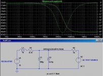
for 28mApk, then CCS=72mA just meets this requirement, but is it a requirement for the test?If the applied test voltage is 20Vac then the peak currents being injected and extracted from the PSU are ~+-28mApk .i.e. 30Vdc across 1k0
If this applies, then the CCS must be set to pass ~>= [2 * Ipk] + Iq.
Tempco of the regulator
I am not sure how important temperature stability is for a general purpose regulator but if Vbe of Q3 has a tempco of ca. -2 mV/K and a typical 12 V Zener (BZX55) +3 to +11 mV/K, and probably closer to the higher value, then this will be +9mv per Kelvin worst case. If I take 30 Volt output voltage this translates to some 22 mV per K output voltage drift (if I got + and – right and understand the circuit in the first place, off course).
A better voltage reference, and potentially a diode under VR 15 could substantially improve this.
Just my 2 cents
Andrew,
Maybe I miss something, but if we stay with the standing current, no load, 75mA just for discussion? With + and - 28mA peak AC, the shunt current varies between 75+28=103mA and 72-28=44mA, is this what you mean?
What is this '30VDC across 1k0' you mentioned? Is this a DC load you assume when doing the test? (I used 1.3k).
If so, then the shunt current varies between 75+28-30=73mA and 75-28-30=17mA? Do we agree?
Jan Didden
I was about to ask... how badly do we also need Q6 ? I'd like to use this reg in a quite low drop out situation (vin-vout at around 2vdc).
Pretty badly, for the bandwidth and impedance of the current source.
You can off course put in wire jumpers across Q6 for a low drop out situation and otherwise keep the better cascoded current source where you do have enough voltage.
AndrewT said:The input CCS as originally shown has a low drop out characteristic.
It can work at about 1.1V
My concern was that with only 2.5V vin-vout, LTspice gives me way worse performance for a cascoded CCS than for a single transistor CCS (something like 80db vs 110db PSSR). I need more than 3V accross the cascoded CCS to get it to work as well as the one-transistor CCS.

Simulation artifact ?
Yes.
The single transistor CCS works with as low as 1.5V
The cascoded CCS works with as low as 2V with a 1n4148 instead of the 100R
The cascoded CCS works with as low as 3.5V with a red led instead of the 100R
Once the correct differential reached and up, the cascoded CCS simulate better but not that much for PSRR (a pair of db). I guess I should try other things (dynamic load) to see the advantages of cascoded CCS.
Sorry we're close but not yet in agreement on the arithmetic.janneman said:Andrew,
Maybe I miss something, but if we stay with the standing current, no load, 75mA just for discussion? With + and - 28mA peak AC, the shunt current varies between 75+28=103mA and 72-28=44mA, is this what you mean?
What is this '30VDC across 1k0' you mentioned? Is this a DC load you assume when doing the test? (I used 1.3k).
If so, then the shunt current varies between 75+28-30=73mA and 75-28-30=17mA? Do we agree?
Jan Didden
Does a 20V through a 1k0 resistor give +-28mApk?
The 75mA draw of the shunt regulator has to supply Iq. Iq is ~13mA through the CCS and ~3mA through R5. This leaves ~59mA to feed the load and the shunt and the test current source/sink.
Using your 1k3 load with 30V across it, the load sinks 23mA. That leaves 36mA to go through the shunt and the current source.
So the nominal shunt current is 36mA+-28mA i.e min~8mA and max~64mA.
Are we in agreement yet?
If we reduce the load resistance to 1k0 and sink 30mA
then the shunt varies from {[75-16] -30]}+-28.4mA~=0.6mA to 57.4mA
I see a problem, the minimum shunt current gets very close to zero and depends very much on a difference of two similar but large currents.
There's the reason for my original question. I fear we must be very careful to ensure the test AC current source/sink does not take the shunt beyond it's operational limits.
- Status
- This old topic is closed. If you want to reopen this topic, contact a moderator using the "Report Post" button.
- Home
- Amplifiers
- Solid State
- Bipolar discrete shunt regulators